Cip - communications capabilities, Watlow ez-zone, Rui/gateway – Watlow EZ-ZONE RUI/Gateway User Manual
Page 35
Watlow EZ-ZONE
®
RUI/Gateway
•
32
•
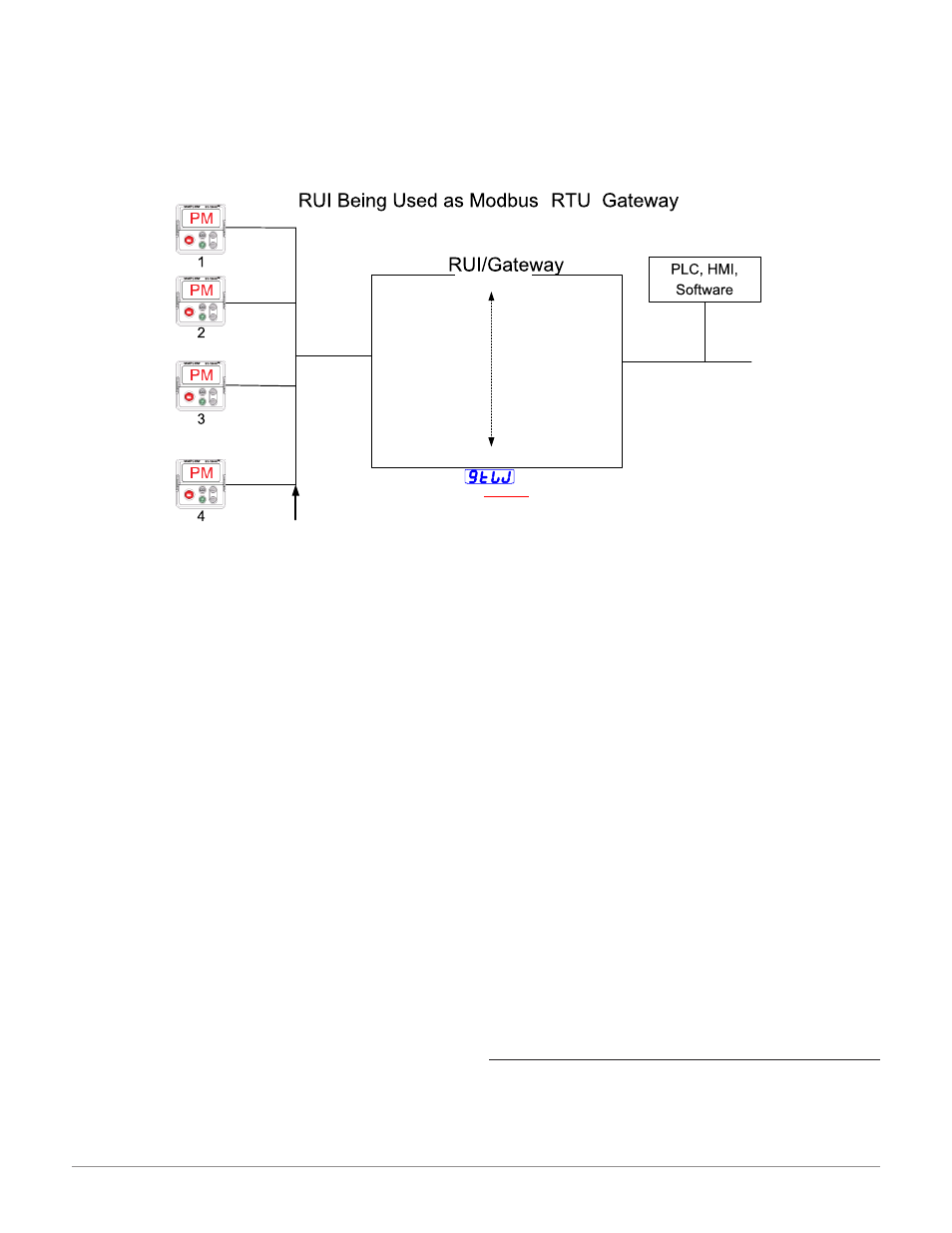
Chapter 5 Networking with a Gateway
Assembly Definition Addresses
- Fixed addresses used to define the parameter that
will be stored in the "Working Addresses", which
may also be referred to as a pointer. The value
stored in these addresses will reflect (point to) the
Modbus address of a parameter within the con-
troller.
Assembly Working Addresses
- Fixed addresses directly related to their associated
Assembly Definition Addresses" (i.e., Assembly
Working Addresses 200 & 201 will assume the the
parameter pointed to by Assembly Definition Ad-
dresses 40 & 41).
When the Modbus address of a target parameter is
stored in an "Assembly Definition Address" its cor-
responding working address will return that parame-
ter’s actual value. If it’s a writable parameter, writing
to its working register will change the parameter’s
actual value.
As an example (using the EZ-ZONE ST Users
Guide), Modbus register 360 and 361 (Map 2) con-
tains the Analog Input 1 Process Value (See Opera-
tions Page, Analog Input Menu). If the value 360 and
361 is loaded into Assembly Definition Addresses 90
and 91, the Process Value sensed by Analog Input 1
will also be stored in Modbus registers 250 and 251.
Note that by default this parameter is also stored in
working registers 240 and 241 as well.
Note:
When changing the assembly as in the example
above a multi-write function must be used, i.e.,
writing 360 to register 90 and 361 to register 91. All
members in the assembly are 32 bits.
The table identified as " Modbus Programmable
Memory Blocks" found in the appendix of this Users
Guide reflects the assemblies and their associated ad-
dresses.
To learn more about the Modbus RTU protocol point
your browser address below:
http://www.modbus.org
Note:
To minimize traffic and enable better throughput
on Standard Bus, set the Number of Zones prompt
[nU;2n]
in the RUI to the maximum number of EZ-
ZONE controllers on the network to be scanned.
Note:
The logic used when determining the Modbus offset
is based on the number of Modbus addresses need-
ed for any given controller. In the above example,
each PM controller would have access to the first
5000 Modbus registers (400001 - 405001).
Note:
If using a legacy EZ-ZONE ST controller with a
firmware version less the 3.0, consider using the
Modbus addresses listed in the ST Users Guide
in the column entitled "RUI/GTW Modbus". If the
firmware in the ST is 3.0 or higher new features
were added and made accessible through the Map
2 registers. If interested in using the new features
today or perhaps in the future configure the ST for
Map2 Modbus registers.
CIP - Communications Capabilities
Communications using CIP (EtherNet/IP and De-
viceNet) can be accomplished with any EZ-ZONE con-
troller using an RUI/GTW. Reading or writing when
®
[gtW]
1 = PM1
[gtW]
4 = PM4
Baud Rate
[baud]
= 9.6, 19.2, 38.4Kb
[Com]
Instance 2
Parity
[par]
= [none], [euen], [odd]
Modbus
®
RTU
Watlow Standard Bus
(Daisy chain EIA-485)
EZ-ZONE
®
Controllers
1 - 16 maximum
Modbus
®
Offset
* 15000
Modbus
®
Offset
* 10000
Modbus
®
Offset
5000
Modbus
®
Offset
0
* The RUI allows for a maximum entry of 9999 due to the limitations of the 7 segment display. To enter an offset > 9999
EZ-ZONE
®
configurator software must be used.
Modbus
®
Address
[ad;m]
= 1 - 247
Modbus
®
Word Order
[M;hl]
= [lohi] or [hilo]
[Com]
Instance 1
Standard Bus Address
[Ad;S]
= 1-8
Start Node to Scan
[St;2n]
= 1-24
End Zone to Scan
[nU;2n]
= 1-24
RUI/Gateway
Setup Prompts
[gtW]
= 1 – 16
(Gateway Instance)
[Du;En]
= Yes or No
(Enable gateway instance)
Gateway
[Du;st]
= [On] or [off]
(Device Status)
[M;of]
= 0 – 65535
*
(Modbus
®
Offset)
Units
[`C_f]
= [``f] or [``C]