IEI Integration WAFER-945GSE v1.04 User Manual
Page 75
WAFER-945GSE 3.5” Motherboard
Page 55
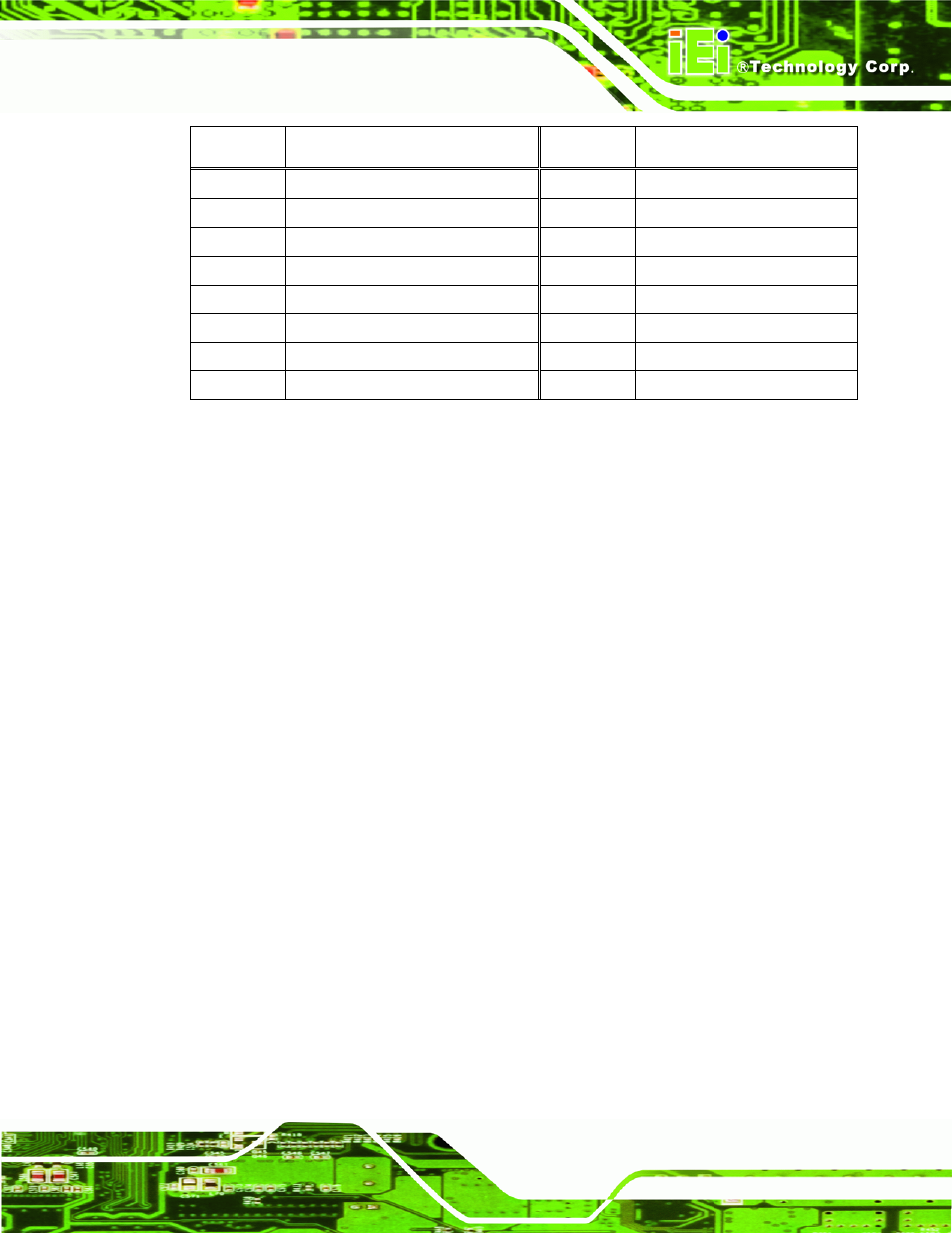
PIN NO.
DESCRIPTION
PIN NO.
DESCRIPTION
25
TRANSMIT DATA (TXD5)
26
CLEAR TO SEND (CTS5)
27
DATA TERMINAL READY (DTR5)
28 RING
INDICATOR
(RI5)
29 GND
30 GND
31
DATA CARRIER DETECT (DCD6
32
DATA SET READY (DSR6)
33
RECEIVE DATA (RXD6)
34
REQUEST TO SEND (RTS6)
35
TRANSMIT DATA (TXD6
36
CLEAR TO SEND (CTS6)
37
DATA TERMINAL READY (DTR6
38
RING INDICATOR (RI6)
39 GND
40 GND
Table 4-17: COM3 to COM6 Connector Pinouts
4.3.16 Serial Port Connector (COM 2)(RS-232, RS-422 or RS-485)
CN Label:
COM2
CN Type:
14-pin header (2x7)
CN Location:
See
761H
Figure 4-17
CN Pinouts:
See
762H
Table 4-18
The 14-pin serial port connector connects to the COM2 serial communications channels.
COM2 is a multi function channel. In default mode COM2 is an RS-232 serial
communication channel but, with the COM2 function select jumper, can be configured as
either an RS-422 or RS-485 serial communications channel.
- SPCIE-5100DX (180 pages)
- SPCIE-C2060 v1.01 (200 pages)
- SPCIE-C2060 v2.12 (212 pages)
- SPCIE-C2160 (204 pages)
- SPCIE-C2260-i2 (217 pages)
- ROCKY-3786 v4.0 (175 pages)
- ROCKY-3786 v4.10 (147 pages)
- PCIE-Q350 v1.00 (272 pages)
- PCIE-Q350 v1.12 (250 pages)
- PCIE-Q350 v1.20 (250 pages)
- PCIE-Q350 v1.30 (213 pages)
- PCIE-Q57A (159 pages)
- PCIE-G41A2 (151 pages)
- PCIE-Q670 v1.03 (206 pages)
- PCIE-Q670 v2.00 (205 pages)
- PCIE-H610 (181 pages)
- PCIE-Q870-i2 (217 pages)
- IOWA-LX-600 (159 pages)
- PCISA-945GSE v1.01 (207 pages)
- PCISA-945GSE v1.10 (190 pages)
- PCISA-9652 v1.00 (232 pages)
- PCISA-9652 v1.01 (232 pages)
- PCISA-PV-D4251_N4551_D5251 (145 pages)
- PICOe-945GSE (197 pages)
- PICOe-GM45A (198 pages)
- PICOe-PV-D4251_N4551_D5251 v1.00 (154 pages)
- PICOe-PV-D4251_N4551_D5251 v1.10 (154 pages)
- PICOe-PV-D4251_N4551_D5251 v1.11 (155 pages)
- PICOe-B650 (156 pages)
- PICOe-HM650 (174 pages)
- HYPER-KBN (139 pages)
- SPXE-14S (3 pages)
- SPXE-9S v1.00 (5 pages)
- SPXE-9S v1.1 (6 pages)
- SPE-9S v1.00 (4 pages)
- SPE-9S v1.1 (5 pages)
- SPE-6S (3 pages)
- SPE-4S (4 pages)
- PE-6SD3 (4 pages)
- PE-6SD2 v4.0 (4 pages)
- PE-6SD2 v2.10 (3 pages)
- PE-6SD (3 pages)
- PE-6S3 v1.0 (2 pages)
- PE-6S3 v4.0 (4 pages)
- PE-6S2 (4 pages)