Device viewer – TREND 963 User Guide User Manual
Page 12
About 963
963 User Guide TC200635 Issue 3 25/03/2008
12
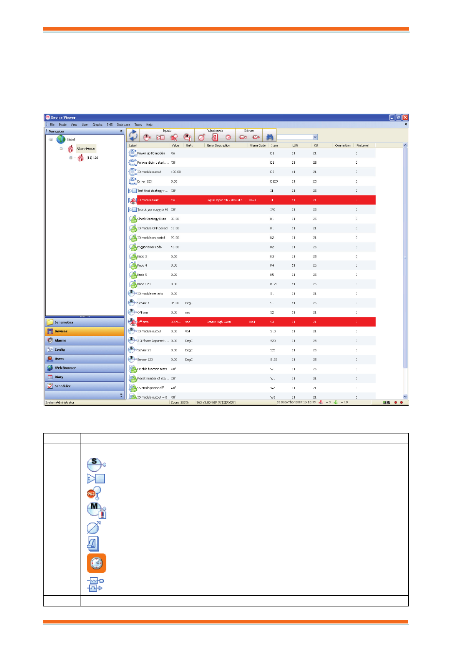
2.1.1.3 Device
Viewer
The Device Viewer, shown below, enables inputs, outputs, adjustments, time zones, and critical alarms from the
part of the system selected in the Navigator to be displayed, and for values to be adjusted, or graphed. E.g. if the
internetwork is selected, all values from the internetwork are displayed. If a particular Lan is selected only values
from that Lan are displayed. The display can be filtered further so that only modules whose label matches a search
string are displayed. The display is colour coded to indicate whether the alarm is current. Red indicates that the
alarm is current. Once the values have been displayed it is possible to adjust values, or display a graph.
It contains a number of columns that display the values of the inputs, outputs, adjustments, time zones, and critical
alarms.
Column Description
Icon
Contains an icon that indicates the module type.
Sensor Modules
Digital Input Modules
Virtual Sensor Modules
Critical Alarm Modules
Knob Modules
Switch Modules
Time zone Modules
Analogue Driver Modules
Digital Driver Modules
Label
The module label.