Probus interface – Teledyne LeCroy WavePro 7 Zi_Zi-A User Manual
Page 29
Getting Started Manual
922137-00 Rev A
21
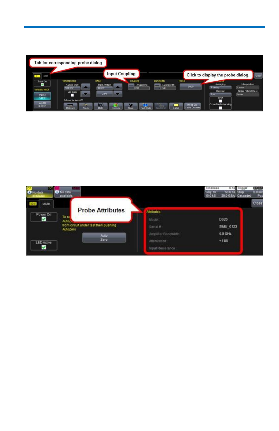
When a probe is connected, it is recognized and an additional tab with the
probe model name is displayed to the right of the C1 tab.
The channel dialog layout showing Input A's ProLink interface controls setup
after connection.
This additional tab contains specific information on the connected probe.
In addition, default values for the probes coupling and attenuation (which
may not be changed) are automatically downloaded from the probe, and
these settings along with other attributes are shown on the corresponding
probe dialog.
The dialog showing the connected probe's control attributes.
ProBus Interface
The ProBus interface contains a 6-pin power and communication
connection and a BNC signal connection to the probe. It offers both 50 Ω/1
MΩ input impedance and provides probe power and control for a wide
range of probes such as high impedance passive probes, high impedance
active probes, current probes, high voltage probes, and differential probes.
ProBus also includes sense rings for detecting passive probes. The ProBus
interface may also have a BNC-terminated cable connected directly to it.
ProBus is based on a BNC connector and, depending on the exact BNC
connector used and the oscilloscope design, is rated for up to 4 GHz with
50 Ω coupling or up to 1 GHz for 1 MΩ coupling (depending on the exact
model purchase).