The pipe system – System Sensor FAAST Comprehensive User Manual
Page 29
The pipe System
ComprehenSive inSTruCTion mAnuAl
SCope
This section provides details on the physical installation of the pipe network
for the FAAST system. Knowledge of local codes and regulations is required in
addition to this manual.
inSTAllATion STAGeS
Table 1 lists the standard installation stages for an aspiration pipe network.
TABle 1. TYpiCAl pipe neTWorK inSTAllATion proCeDure
STep
ACTion
1
Verify design documents are accurate and obtain the size and
configuration of the pipes in the network .
Note: If PipeIQ was used to design the network, a bill of materials
can be generated from the application .
2
Mark off the area where the system is to be installed and identify
the location where the FAAST detector is to be mounted .
3
Select and mark the locations for the pipe clips in accordance with
the design .
4
Install the FAAST detector in its permanent location . (See
Installation and Maintenance Guide for details .)
5
Mount the pipe clips according to the previous markings .
6
Dry mount and assemble the pipe network according to the pipe
network design documents .
CAUTION: Do not permanently connect the pipes at this time .
7
Measure and mark the sampling holes on the pipe network . Make
sure that the spacing of the sampling holes is in accordance with
the network design . Based upon the application, ensure that the
sampling holes are at the correct orientation to the air flow, as rec-
ommended in the section on network pipe design .
8
Verify the sampling-hole positions and orientations and drill the
sampling holes .
9
Drill and install end caps on all appropriate pipe ends .
10
Modify the design documents to agree with the actual network,
if the physical network is significantly different from the original
design documents .
11
When testing is complete and the system performance is verified,
permanently bond the pipe network together .
CAUTION: Never bond the pipes to the detector .
The detector
inlet and outlet are tapered to accept the piping without any bond-
ing and provide an air tight seal .
12
Label all portions of the system according to local codes and regu-
lations . Pipe and Sampling Point labels are available –
refer to the Accessories section .
13
If additional changes are made, ensure that design documents
are updated accordingly .
pipe neTWorK ComponenTS
The FAAST detector uses standard aspiration fire detection pipe network com-
ponents, such as pipes, elbows and couplings. The components listed in this
section are not an all inclusive list of components used for fire protection sys-
tems. However, they represent the most commonly used items.
pipeS
The pipes used in the pipe network can be made of various materials includ-
ing copper, PVC, ABS, UPVC and CPVC. The internal pipe diameter used with
the FAAST system can range from 0.591 to 0.827 in. (15 to 21 mm). Ideal
dimensions vary depending on system design requirements, as well as local
codes and regulations. The FAAST detector has a built in tiered insertion point
for the pipes, which allows for an outside tube diameter of either 1.050 in. or
25 mm to accommodate U.S. Customary System and Metric System sized pipe.
FiTTinGS
Fittings are used to connect sections of pipe together on longer network runs
and are made from the same material as the pipe. There are several types of
fittings to allow for various bends, straight runs, branches and connections.
Common fittings are described in the following sections.
Couplings and unions
Couplings and unions are used to connect two sections of pipe in a straight
line. A coupling is used when the section is not intended to be taken apart.
A union offers the ability to screw the two pipe sections together for future
access, such as areas of the pipe network that have to be periodically dis-
assembled for maintenance or cleaning. Unions can also be used to orient
sample holes correctly in a specific section of the pipe network, such as over
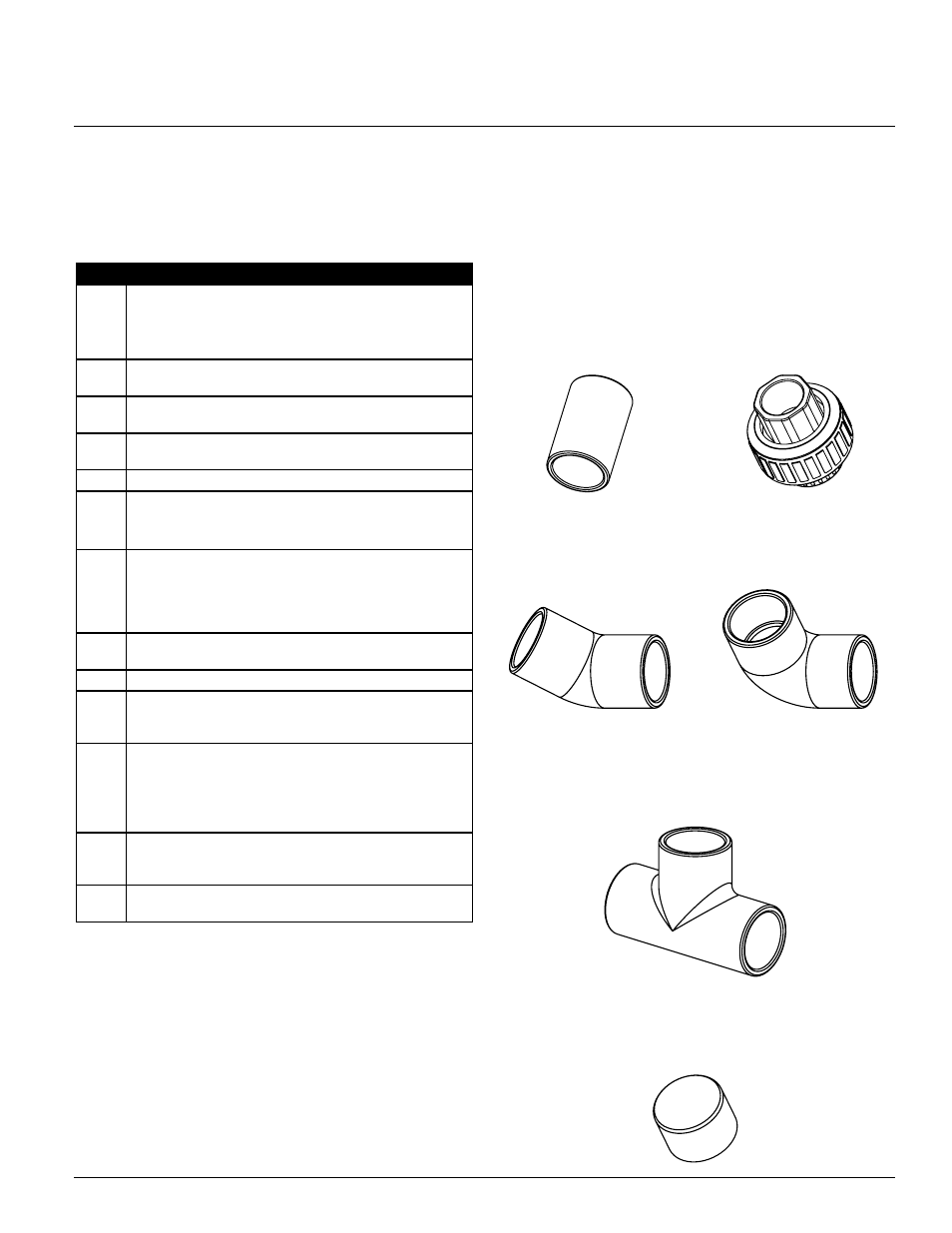
return air grilles. Figure 1 shows a typical union and coupling.
FiGure 1. TYpiCAl union AnD pipe reDuCer
FiGure 2. 45 AnD 90 DeGree elBoWS
45°
90°
FiGure 3. Tee
FiGure 4. enD CAp
ASP-76
ASP-77
ASP-80
ASP-79
ASP-75
ASP-78
elbows
Elbows are used to change the direction of the pipe network. Both 45 degree and
90 degree elbows may be used. Both elbow fittings are shown in Figure 2.
Tees
Tees are used for attaching drop tubes or sampling pipes in the network.
A specialized tee can be used to attach a capillary tube and a sampling point.
A tee is shown in Figure 3.
end Caps
The end of the pipe should be terminated with an end cap. The end cap may
have a sampling hole depending upon the system design. The size of the hole
in the end cap is determined by the PipeIQ software. An end cap is shown in
Figure 4.
SS-400-007 30 E56-3621-003
The Pipe System