System Sensor P12015K Outdoor Horn_Strobe User Manual
Spectralert outdoor horn/strobe, Installation and maintenance instructions
General Description
The SpectrAlert series notification appliances are designed to
meet the requirements of most agencies governing these devices,
including: NFPA, The National Fire Alarm Code, UL, CSFM, MEA.
Also, check with your local Authority Having Jurisdiction for other
codes or standards that may apply.
The P12015K must be installed using a 120 VAC power source. This
unit can only be used for non-synchronous applications. This unit
will NoT work with SpectrAlert Sync•Circuit Modules.
NOTICE: This manual shall be left with the owner/user of this
equipment.
Fire Alarm System Considerations
Temporal and Non-Temporal Coded Signals:
The American National Standards Institute and the National
Fire Alarm Code require that all horns used for building evacu-
ation installed after July 1, 1996, must produce Temporal Coded
Signals.
Signals other than those used for evacuation purposes do not have
to produce the Temporal Coded Signal. Temporal coding is accom-
plished by interrupting a steady sound in the following manner:
Current Draw Measurements – Both Horn and Strobe
Maximum Current Limit: 261.6mA RMS (as measured by UL)
D900-26-00
1
I56-1792-002R
SpectrAlert Outdoor Horn/Strobe
For use with model: P12015K
The Products to which this manual applies may be covered by one or more of the
following U.S. Patent numbers: 5,914,665; 5,850,178; 5,598,139; 6,049,446; 5,593,569; 6,133,843
INSTALLATION AND MAINTENANCE INSTRUCTIONS
3825 ohio Avenue, St. Charles, Illinois 60174
1-800-SENSoR2, FAX: 630-377-6495
www.systemsensor.com
Specifications
Rated Voltage:
Regulated 120 VAC
operating Voltage Limits:
96-132 VAC
NOTE: Combo units will operate on walk tests with on-time durations of 1 sec. or greater.
Flash Rate:
1 Flash Per Second
operating Temperature:
Horn/Strobes have a temperature range of -40°F to 150°F (-40°C to 66°C) and are rainproof per UL50
(NEMA 3R).
Horns are indoor/outdoor listed per UL464.
Strobes are indoor/outdoor listed per UL1638.
Light output:
Listed at 15 candela (2.78cd @ -40°C).
Sound output:
Sound output levels are established at Underwriters Laboratories in their reverberant room. Always use
the sound output specified as UL Reverberant Room when comparing products.
Listings:
UL S4011 and S3593
1
/
2
Sec.
On
1
/
2
Sec.
Off
1
/
2
Sec.
On
1
/
2
Sec.
Off
1
/
2
Sec.
On
1
1
/
2
Sec.
Off
Repeats
Horn Selections
Horns are factory set for temporal code and electromechanical
tone.
Tones:
Two tones may be selected using the DIP switch (see Figure 1)
located on the printed circuit board. With the switch off, the
tone is the Electromechanical sound. With the switch on, the
tone is a 3 kHz sound.
Temp/Non-Temp:
Temporal coding or Non-Temporal coding can be selected
using the DIP switch located on the printed circuit board.
With the switch off, the tone pattern is the Temporal
Coded Signal. With the switch on, the Non-Temporal
code (continuous) tone is active.
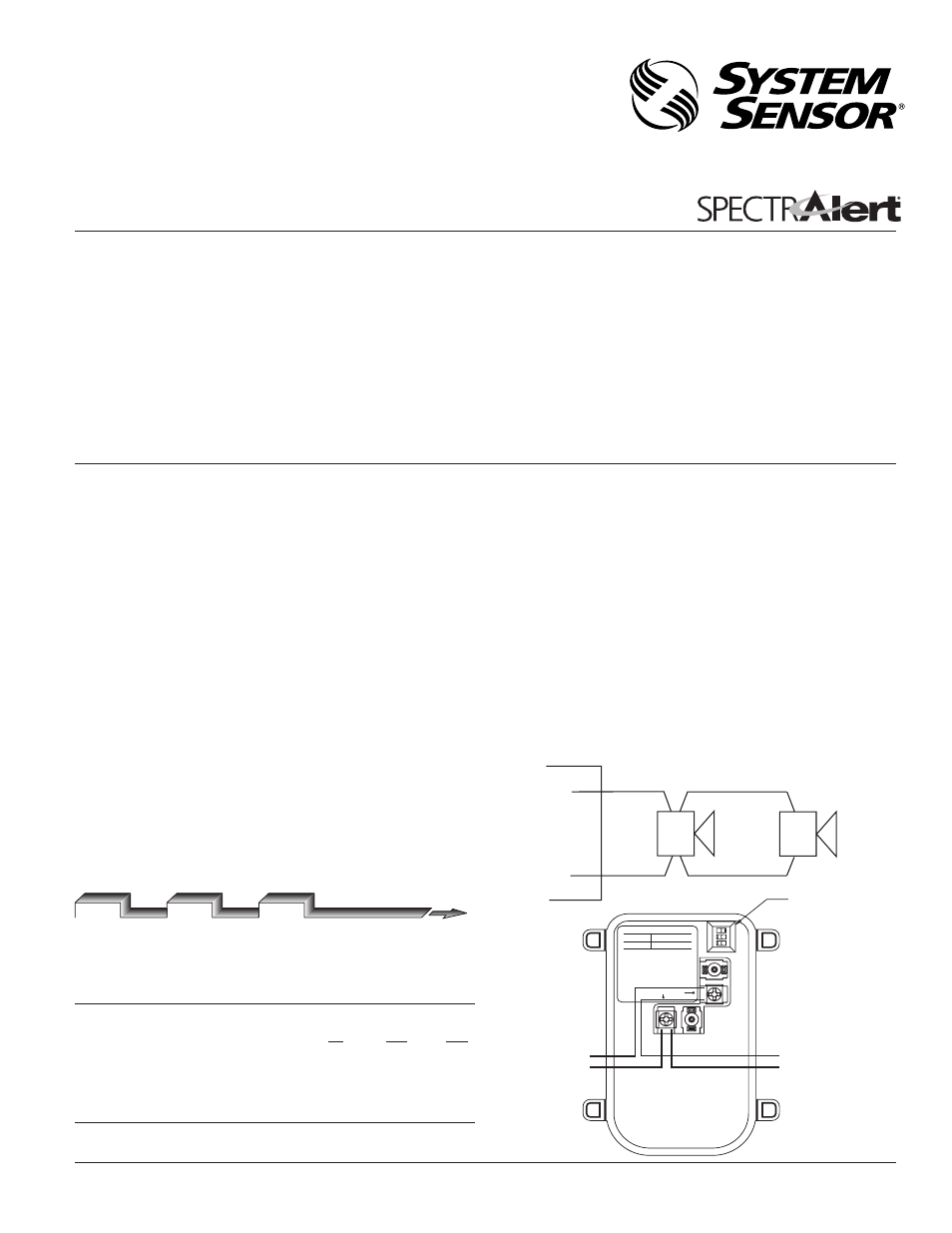
System Operation
Figure 1 (Note: power inputs are non-polarized):
Sound Output Guide UL Reverberant Room dBA@ Volts AC RMS
96
120
132
Temporal
Electromechanical
78
78
78
3000 Hz Interrupted 79
79
79
Non-Temporal
Electromechanical
83
83
83
3000 Hz Interrupted 84
84
84
DIP SWITCH
NOTE: VOLUME SWITCH
DOES NOT OPERATE
TO NEXT DEVICE
FROM AC SOURCE
AC POWER
NOT USED
TEMPORAL NON-TEMPORAL
EM
3kHz
OFF
ON
1
O
N
2
3
STROBE (–)
MODULE (–)
STROBE (+)
MODULE (+)
HORN/STROBE
120 VAC
POWER
A0239-00
A0240-00