System Sensor FAAST Comprehensive User Manual
Page 21
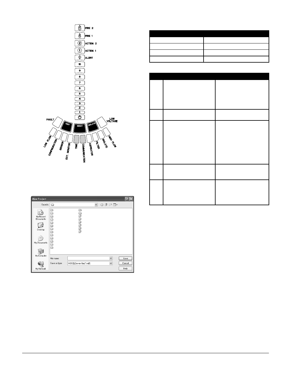
FiGure 8. TYpiCAl STABiliZeD FronT pAnel inDiCATorS
3. Create a project using an appropriate title, as shown in Figure 9, by select-
ing File>New from the menu in the upper left corner of the window, or
by selecting the icon for a new project. To retain information from a previ-
ous project, open the project file associated with the system by selecting
File>Open and then choosing the appropriate project name.
4. Connect to the system by right clicking on the device in the left pane and
selecting “Connect Device.” For an existing device, the text box should have
the Host IP address that was assigned to that device when it was originally
configured. Select Administrator from the drop down menu in the User text
box and enter the password for that device in the Password text box. Select
the Connect button and the icon should change from a red X to a green con-
nect icon showing the device made a successful connection.
5. Double click on the Device icon in the left pane to open the Configuration
window in the right pane. Fill in the appropriate General information, as
shown in Figure 6. Be sure that all of the information selected and entered
is in accordance with local codes and regulations.
Refer to tables 2 through 7 that explain the information contained in the fields
of the General tab.
6. Continue by doing the same steps described in the Commissioning a New
FAAST System, starting with Step 11 of the Commissioning Section
FiGure 9. neW proJeCT SCreen
TABle 11. ApproveD SimulATeD SmoKe proDuCTS
TABle 12. CAnneD SmoKe TeST
mAnuFACTurer
moDel
Home Safeguard Industries
25S
SDi
CHEK02 and CHEK06
SDi
SOLOA4
SDi
SMOKESABRE-01
STep
ACTion
veriFiCATion
1
Make sure that the local fire
panel and any automatic extin-
guishing or suppressant sys-
tems are either disconnected or
isolated from external reporting
equipment
2
Establish that the system is
working normally
Observe the user interface
3
Release simulated smoke
(Home Safeguard Industries
Model 25S or equivalent) near
the sampling hole at the fur-
thest point from the FAAST unit .
Release simulated smoke for
a period of 2 seconds within a
distance of 6 inches directly at
the sampling hole .
Use a stopwatch to measure
the elapsed time between the
release of the simulated smoke
and the first indication of an in-
crease in the particulate level as
indicated on the Particulate Level
display . Record the time on the
Commissioning Form
4
Verify that the alarm re-
lays activate when the alarm
indicators illuminate
Observe the user interface
5
Make sure to re-connect the lo-
cal fire panel and any automatic
extinguishing or suppressant sys-
tems after successful completion
of the test
TeST SYSTem
All FAAST systems must be tested after installation and periodically thereafter.
Testing methods must statisfy the authority having jurisdiction. Systems of-
fer maximum performance when tested and maintained in compliance with
NFPA 72.
preparation for Testing
Prior to any test of a building’s fire alarm system, all occupants should be
notified, in accordance with NFPA 72. This ensures that everyone is aware of
what is going on and the testing can be conducted efficiently. Typically, a team
of two performs testing of a FAAST system, with one technician remaining at
the detector to verify test results, while the other technician introduces the
canned smoke into the farthest sensing hole of the system.
Before these tests are carried out, ensure that the room or area being protected
is in its operational state in terms of airflow, temperature and cleanliness.
Any air handling units should be running, all floor and ceiling tiles should be
installed and any equipment producing a heat load should be in its normal
operating mode.
For proper testing, one of the simulated smoke products listed in Table 12
must be used. A canned smoke test procedure is indicated in Table 13.
System pressure Testing
Pressure testing should be performed on as many sample holes as possible
during the initial commissioning tests. This establishes a good baseline to use
at a later date. During maintenance testing, only a few holes need to be tested
if they continue to be close to the initial results.
During normal system maintenance, verify the current pressures versus the
original pressures for the same sample holes. Any significant differences
should be immediately investigated to determine the cause and potential re-
pair of the system.
ASP-34
ASP-26
SS-400-007 21 E56-3621-003
Commissioning