System Sensor SP201K Outdoor Dual Voltage Transformer Speakers User Manual
Correct
D900-41-00
1
I56-2610-002R
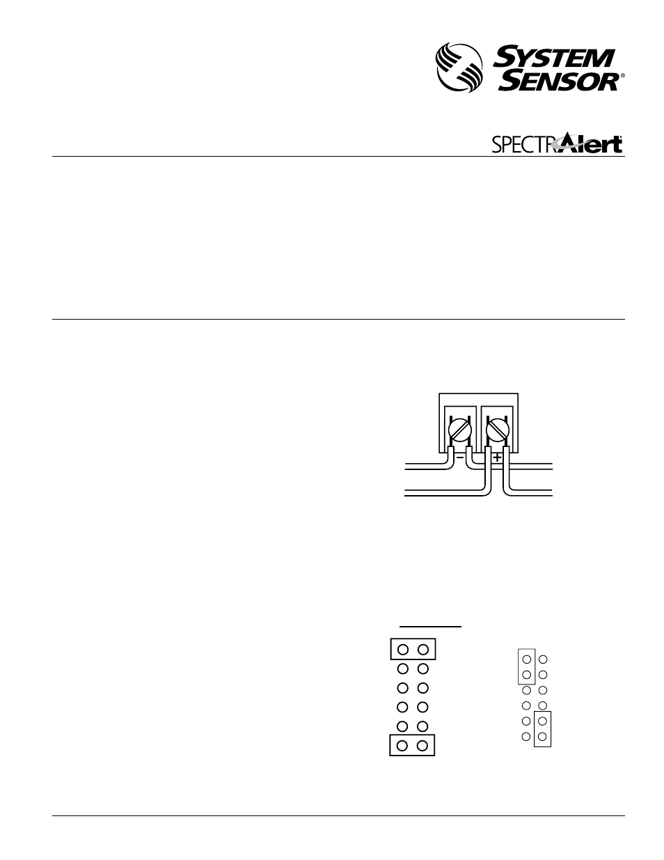
Figure 2:
Specifications
Mechanical
Input Terminals:
12 to 18 AWG (3.31 to 0.82 mm
2
)
Speaker Size:
4 inches (101 mm)
Grille Size:
4
13
/
16
˝ (122 mm)
Outdoor Back Box:
6
5
/
8
˝Ч5
1
/
4
˝Ч4˝
Electrical
Voltage Input:
25 volts or 70.7 volts (nominal)
Frequency Range:
400 – 4000 Hz
Operating Temperature Range:
– 40°F to 150.8°F (– 40°C to 66°C)
Maximum Supervisory Voltage:
50 VDC
Input Power Settings:
1
/
4
,
1
/
2
, 1 and 2 Watts
Listings:
UL 1480; NEMA 3R
Figure 1. Electrical connections:
NOTICE: This manual shall be left with the owner/user of this
equipment.
Suitable for outdoor use in wet environments with outdoor back
box supplied with the product.
General Description
The National Fire Protection Association (NFPA) has published
standards and recommended practices for the speakers described
in this manual. As a result, the installer must be familiar with
these requirements as well as all local codes and special require-
ments of the authority having jurisdiction.
SP201K series speaker can be operated with distribution ampli-
fiers having an output voltage of either 25 volts or 70.7 volts.
The speaker operates at any one of four input power levels. The
output sound level is selected at the time of installation, but can
be changed, if necessary.
The speaker is also equipped with a capacitive input to allow for
DC supervision.
Installation
All wiring must be installed in compliance with the National
Electrical Code (NEC) and applicable local codes as well as
special requirements of the authority having jurisdiction, using
the proper wire size. This also includes all applicable NFPA
Standards, ANSI/UL 1480, and NEC 760.
Electrical
1. Connect the speaker as shown in Figure 1.
NOTE: Do not loop electrical wiring under terminal screws. Wires
connecting the device to the control panel must be broken
at the device terminal connection in order to maintain
electrical supervision.
2. See Figure 2 as an example of how to select a
1
/
4
Watt input
when a 25 volt amplifier is being used. Notice that the header,
SW1, has two shunts. One shunt is used to select either 25 or
70.7 volts input. The other shunt is used to select input power
of
1
/
4
,
1
/
2
, 1 or 2 Watts.
3825 Ohio Avenue, St. Charles, Illinois 60174
800/736-7672, FAX: 630/377-6495
www.systemsensor.com
INSTALLATION AND MAINTENANCE INSTRUCTIONS
SpectrAlert SP201K Outdoor
Dual Voltage Transformer Speakers
for Fire Protective Signaling Systems
U.S. patent number: D424465
INPUT FROM
AMPLIFIER
TO NEXT
SPEAKER OR EOL
25.0V
70.7V
2W
1W
1/2W
1/4W
25.0V
70.7V
2W
1W
1/2W
1/4W
CORRECT
SW1
SW
1
INCORRECT
A0175-00
A0102-00
I56-2610-002R