System Sensor FAAST Comprehensive User Manual
Page 20
AlArm
level
ThreSholD
hiGh
SenSiTiviTY
ThreSholD
loW
SenSiTiviTY
CurrenT level
Alert
Alert High
Alert Low
Acclimate Alert Level
Action 1
Action 1 High
Action 1 Low
Acclimate Action 1
Level
Action 2
Action 2 High
Action 2 Low
Acclimate Action 2
Level
Fire 1
Fire 1 High
Fire 1 Low
Acclimate Fire 1 Level
Fire 2
Fire 2 High
Fire 2 Low
Acclimate Fire 2 Level
TABle 7. AlArm level BounDArY DeSCripTionS
When creating a new project, the Alarm Delay and Threshold fields contain
default values. These settings may be modified to meet local codes and regula-
tions. To modify these settings, select the field, highlight the value shown and
enter the desired value.
The Alarm Delay fields are set to a default value of zero. To modify this value,
highlight the value and enter the desired value.
In normal operation, the Night mode allows separate start and end times,
which can be set for day, night and weekend operation. To set the Night mode,
highlight the hour and click on the up or down arrows to set the hour. Repeat
for the minute, second and AM/PM settings for both the start and end times.
14. When the information on this screen is complete, select the save icon to
save the changes.
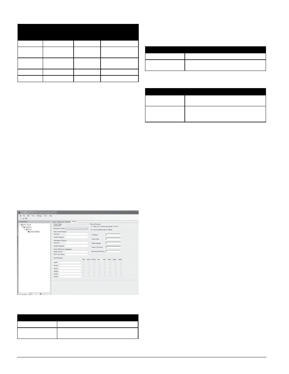
15. Select the Network tab at the top of the window and complete the neces-
sary information for the system, as shown in Figure 7. Be sure that all of
the information selected and entered is in accordance with local codes and
regulations.
The Device Details area contains the serial number of the detector and an
identification number (1 – 255). The user may choose any identification num-
ber within the number range. The serial number is assigned at the factory and
cannot be changed.
For more information see the networking white paper at systemseensor.com/faast.
Tables 9 through 11 provide descriptions of the password and E-mail accounts.
Note that the password character strings are case sensitive. Passwords may be
changed in any of the password fields by typing and confirming a password
once Administrative access has been acquired.
TABle 8. WeB ACCeSS pASSWorD FielD DeSCripTionS
TABle 9. ADminiSTrATor pASSWorD FielD DeSCripTionS
TABle 10. DeviCe e-mAil Server ConFiGurATion FielD
DeSCripTionS
FielD
DeSCripTion
Passcode
User can input up to a 16-character string
Confirm Passcode
User must enter the same character string again to
confirm it
FielD
DeSCripTion
Passcode
Administrator can input up to an 8-character string
Confirm Passcode
User must enter the same character string again to
confirm it
FielD
DeSCripTion
Sender Account
E-mail address from which the device
messages originate
SMTP Server Name
Determine the SMTP server being used and type the
SMTP server name in the field . Contact system admin-
istrator if necessary
The Device Connection area allows the user to choose either DHCP or static IP
addresses for device communication. Choosing the DHCP button deactivates
the IP settings. If a static IP address is selected, enter the IP Address, Subnet
Mask and the Default Gateway fields with the proper information (contact
system administrator if necessary). Primary and Secondary DNS Server ad-
dresses are required if address resolution of the SMTP server is desired.
The E-mail Notification area allows the user to type in up to six E-mail ad-
dresses. These addresses are notified when an the selected event is triggered.
The alarm levels reported to each E-mail address can be chosen by selecting
the appropriate alarm level checkboxes for each address.
16. When the information on this screen is complete, a dialog box appears
asking to transfer the configuration changes to the FAAST device. Select
Yes to begin the download.
17. When the download is complete, the detector automatically resets and
begins to take baseline measurements. At this time the system should be
allowed to run undisturbed for at least five minutes to ensure it calculates
valid air flow and filter monitoring baselines. When the system stabilizes,
the front panel indicators are illuminated, as shown in Figure 8. The par-
ticulate level indicators illuminate along with the Test, Reset and Isolate
buttons. The indicators at the bottom of the display indicate the air flow
through the detector. If the system has normal air flow, these indicators
are illuminated in green, near the center of the display.
18. If the location contains more than one FAAST system, repeat this proce-
dure for each system being commissioned at the location.
re-Configuring or updating a FAAST System
When a FAAST detector is configured, certain pipe network specific param-
eters are erased. During the subsequent power-up, the detector will initial-
ize these parameters for the attached pipe network. Once the parameters
are initialized, the detector will operate using these parameters until the next
configuration change. Therefore, it is imperative that the pipe network be
inspected each time the detector is reconfigured. Perform the following proce-
dure to properly re-commission or update a system.
1. If the system fails to power up and stabilize, re-check that all power wiring
is securely and correctly connected.
2. Apply power to the system and open the PipeIQ application. Make sure that
the PipeIQ application is connected to the detector either through a local
network cable or through an internet network connection to the system.
FiGure 7. neTWorK ConFiGurATion TAB
ASP25-01
SS-400-007 20 E56-3621-003
Commissioning