System Sensor FAAST Comprehensive User Manual
Page 10
When the desired changes have been made, select the OK button to close the window.
Highlight the pipe (pipe turns from red to grey) then select and drag the pipe to
the proper location and connect it to the FAAST detector. The pipe color changes
from grey to green to indicate the proper connection between components.
modifying the pipe information
Once the pipe information has been input, the pipe diameter and/or hole
diameter can be modified.
To modify the pipe information, double-click on the pipe that needs changing.
The Pipe Details window shown in Figure 15, opens for the pipe. In the Pipe
Diameter text box, enter the new value. In the Hole Diameter text box, enter
the new value. Select OK at the bottom of the window.
Adding Additional pipes
To add additional pipes to the design, orient the view to any view but Iso,
then highlight the section the pipe will be connected to. The receiving section
will turn yellow. Select and drag the pipe to the proper location and connect
it to the existing pipe. The new pipe color changes from yellow to green to
indicate the proper connection between components.
Auto Connect pipes
Pipes can be automatically connected together by selecting two pipes and
clicking the ‘Connect Pipes’ button on the tool bar.
To select two pipes, click the first pipe then hold the CTRL button on the key-
board and select the second pipe. Both pipes will show the color of a selected
entity (default color is grey). When the ‘Connect Pipes’ button is clicked the
selected pipes will automatically join.
Note: The pipe will automatically connect based on the “top to bottom” or
“left to right” orientation that was selected in the pipe details window.
TeSTinG The pipe DeSiGn
After creating a pipe design, test it to ensure that the design meets the speci-
fied criteria, such as transportation time, pressure, and flow. The values can
be corrected by auto balancing them. This may be done by selecting the Auto
Balance button on the toolbar.
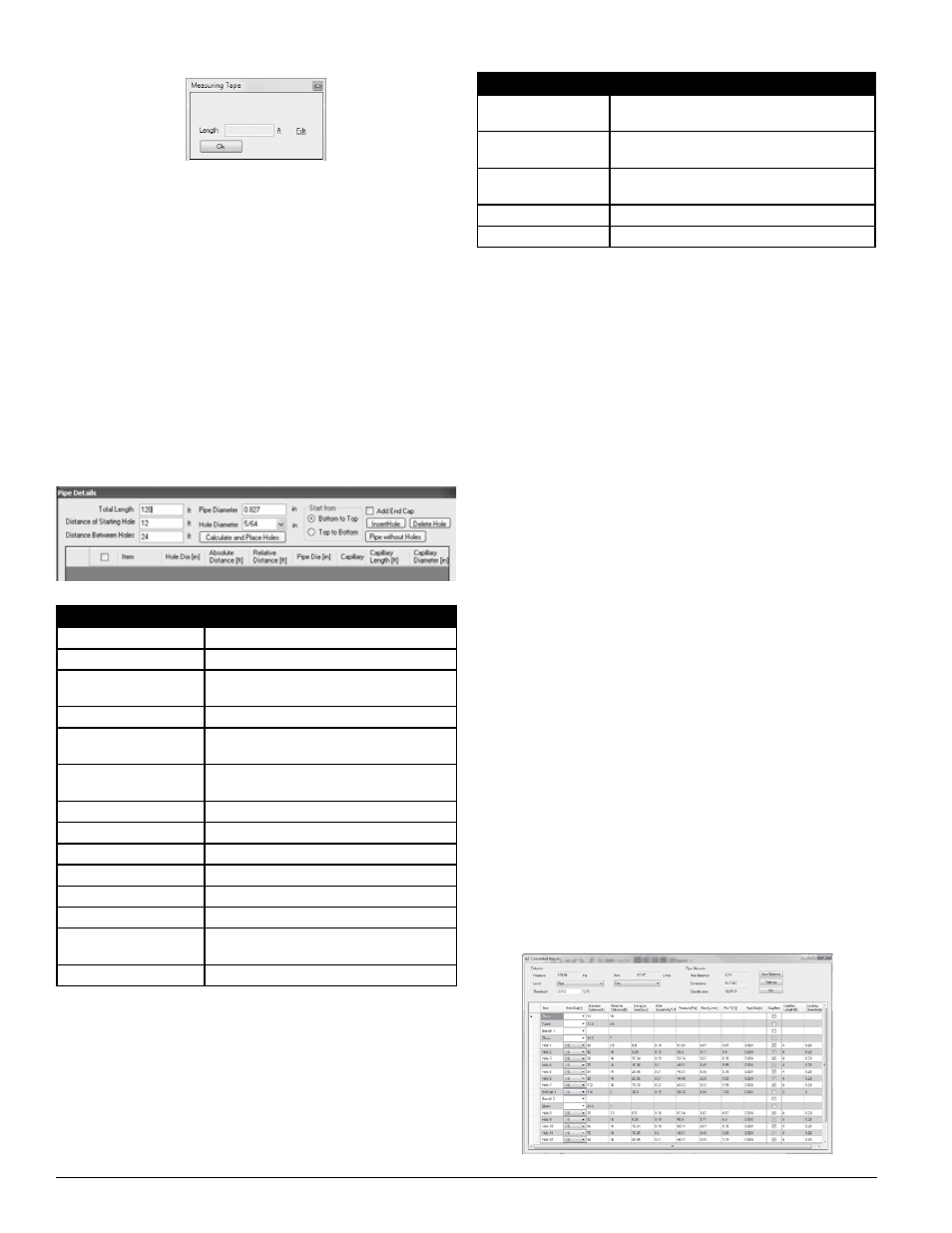
pipe Design Calculation
To calculate the expected performance of the pipe design, select the calculator
symbol. The Calculated Results window, as shown in Figure 16 opens.
If the calculated result for the Transport Time, Pressure, or flow will show red
for any value less than 25 l/min. This may be corrected by manually adjusting
the sampling hole sizes or using the Auto Balance feature. The calculated Hole
Sensitivity is based on the Fire 1 daytime threshold and the expected dilution
from other sampling holes. To improve the effective sensitivity, reduce the num-
ber of holes or decrease the Fire 1 threshold.
ADDinG A DeTeCTor
To add a FAAST detector to the design, select the drawing area, then select the
Detector (FAAST detector) button on the toolbar in the right pane. A FAAST de-
tector must be the first item added to a pipe network design.
ADDinG A pipe
TIP: Before adding a pipe to the system, always highlight the FAAST detector
or pipe that will be connected to the pipe section. This keeps the components
in the same plane of the design field.
Next select the pipe orientation icon (horizontal or vertical ) from the toolbar
that is desired to connect to the detector. The orientation of the pipe is rela-
tive to the view that you have selected. Adding a vertical pipe from the top
view will add a pipe that runs vertically as you are looking at the screen, not
vertically as it appears to the detector. The Pipe Details window will open as
shown in Figure 15. Complete the fields outlined in Table 17. It is important
to specify the direction the pipe will be extending. For example, If a vertical
pipe is chosen for connection to an existing horizontal in order to run towards
the top of the screen, “bottom to top” should be selected. As with adding a
pipe, “bottom to top” or “left to right” are relative to the view you are using
in the drawing area.
FiGure 16. CAlCulATeD reSulTS WinDoW
ASP105-00
SS-400-007 10 E56-3621-003
PipeIQ
FielDS
DeSCripTion
Total Length
Specify the total length of the pipe .
Pipe Diameter
Specify the diameter of the pipe .
Bottom to Top
Select the bottom as the starting point for a
vertical pipe .
Top to Bottom
Select the top as the starting point for a vertical pipe .
Left to Right
Select the left side as the starting point for a
horizontal pipe .
Right to Left
Select the right side as the starting point for a
horizontal pipe .
Add End Cap
Check the box if an end cap is required .
Distance of Starting Hole
Specify the distance of the hole from the front end .
Hole Diameter
Select the diameter of the holes .
Insert Hole
Use to manually insert a hole in the pipe segment .
Delete Hole
Use to manually remove a hole from the pipe segment .
Distance Between Holes
Specify the distance between holes .
Calculate and Place Holes Automatically adds holes to the segment
using the specified settings .
Pipe without Holes
Use to create a pipe with no sample holes .
TABle 17. pipe DeTAilS DeSCripTion oF FielDS
FiGure 15. pipe DeTAilS WinDoW
ASP-45
Select the Calculate and Place Holes button to automatically place the holes
in the pipe. Additonal information about the length of pipe can be modified
as indicated in Table 18. To add or delete a hole from the original design,
check the corresponding row of the hole in the Pipe Details window and
select the Insert Hole or Delete Hole button. To create a pipe without any
holes, select the Pipe without Holes button on the right side of the window.
The pipe will automatically be created to the specified length, the window will
close and return to the pipe design screen.
To make manual modifications to the hole spacing or size, select the check
box in the left column and modify the hole diameter or relative distance be-
tween holes for the selected hole.
TABle 18. pipe hole DeTAilS
FielDS
DeSCripTion
Hole Diameter
Select the diameter of the hole from the pull-down menu
by selecting the down arrow to the right of the field .
Relative Distance
Specify the relative distance of the hole from
other holes .
Capillary
Select the check box to use a capillary tube at the
location where a hole is created .
Capillary Length
Specify the length of the capillary .
Capillary Diameter
Specify the interior diameter of the capillary .
FiGure 14. meASurinG TApe WinDoW
ASP96-00