IAI America ICS(P)A User Manual
Page 38
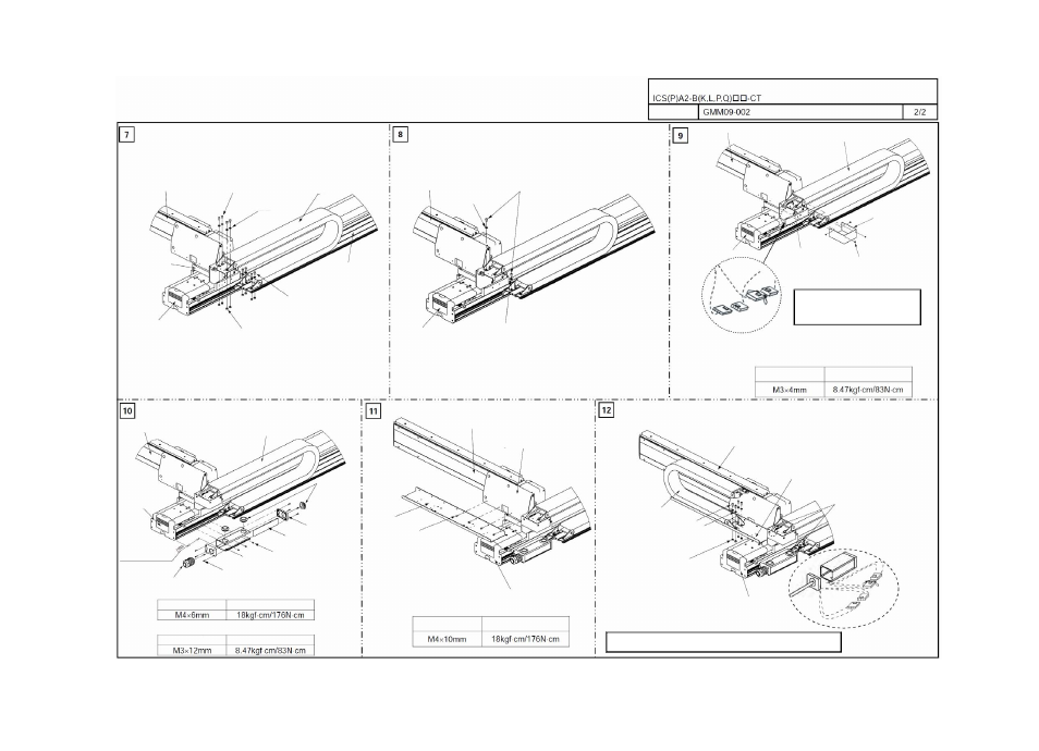
* This assembly procedure applies to combination direction 1. If other combination direction such as 2, 3 or 4 is used, the actuator and bracket directions vary. However, you can still use this assembly drawing as a reference.
Drawing No.
ICS(P)A Cartesian Robot, 2-axis Configuration XYB (Y-axis Base Mount) Type
Cable
Track
X-axis: IS(P)A
Y-axis: IS(P)A
[5] Track mounting
bracket
Hexagonal socket head bolt
(4 pcs) M6 x 10 mm
[6] Cable track
Flat washer
M6 hexagonal nut (8 pcs)
Hexagonal socket head bolt
(4 pcs) M6 x 12 mm
[12] Guide rail
Y-axis: IS(P)A
X-axis: IS(P)A
Tie-mount KR5G5
* Used to install the cable.
Tie-mount KR5G5
Hexagonal socket head bolt
(2 pcs) M4 x 5 mm
Y-axis: IS(P)A
X-axis: IS(P)A
[6] Cable track
[7] Metal cover
Thin-head (4 pcs)
[5] Track mounting
bracket
Connector joint for Y-axis cable and
cable inside cable track [6]
[Installation of metal cover [7] on track mounting bracket [5]]
Tightening torque
Thin-head screw
Y-axis: IS(P)A
[6] Cable track
X-axis: IS(P)A
[4] Grommet
[11] Box cover
[10] Joint cover
Hexagonal socket head bolt
(3 pcs) M4 x 6
[9] Connector box
Hexagonal socket head bolt (8 pcs)
[8] Cable fix cap
Distance between the
base edge surface to
connector box edge
surface
Install the connector box
[6] in T slot on top slot of
the X-axis side surface.
[Installation of connector box [9] on X-axis: IS(P)A]
Hexagonal socket head bolt
Tightening torque
[Installation of connector box [9] on box cover [11]]
Hexagonal socket head bolt
Tightening torque
Hexagonal socket
head bolt
Tightening torque
X-axis: IS(P)A
Hexagonal socket
head bolt (4 pcs)
[12] Guide rail (2)
Y-axis: IS(P)A
[2] X-Y bracket
[Installation of guide rail (2) [12] on X-Y bracket [2]]
Y-axis: IS(P)A
[13] Cable track
Hexagonal socket head bolt
(8 pcs) M6 x 10 mm
Flat washer (4 pcs)
[12] Guide rail (2)
Install the cable
onto the tie-
mount KR5G5.
M6 hexagonal nut (4 pcs)
X-axis: IS(P)A
[6] Connector joint for cable
inside cable track and
controller-actuator cable
Follow “Instruction for Cable Track Type Wiring (Drawing No. GMM12-001)”
for how to lay out the wiring inside a cable track.
Follow “Instruction for Cable Track Type
Wiring (Drawing No. GMM12-001)”
for
how to lay out the wiring inside a cable
track.