IAI America ICS(P)A User Manual
Page 31
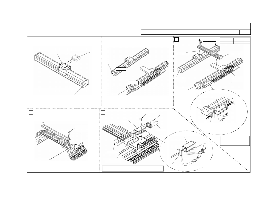
ICS(P)A Cartesian Robot, 3-axis Configuration XYG (Gantry) Type
ICS(P)A3-G
B-CT-CT X-axis/Y-axis: Cable Track, Y-axis/Z-axis: Cable Track
Drawing No.
GMM08-013
2/3
6
7
9
8
10
8 x 18mm
Parallel pin (2 pcs)
(4 pcs)
(2 pcs)
Hexagonal socket
head bolt
Tightening torque
M8x30mm (6 pcs) 54.7 kgf
xcm/536Nxcm
[2] X-Y bracket
[3] Pin bracket
Gantry
Gantry
X-axis: IS(P)A
These 2 pieces
have been deleted.
Gantry
Y-axis: IS(P)A
[11] Cable track
[3] Connector box (large)
Cable inside cable track
Controller-
actuator cable
X-axis: IS(P)A
[8] Cable fix cap
[11] Connector joint for
cable inside cable track
and controller-actuator
cable
X-axis: IS(P)A
Thin-head screw
Y-axis: IS(P)A
[9] Joint cover
[7] Connector box (small)
[8] Box cover
[7] Connector box (small)
[8] Box cover
Connector joint for
actuator cable and cable
inside cable track
M4 x 10 mm (2 pcs)
M3 x 12 mm
M3 x 12 mm
Driven axis
Driving axis
Follow “Instruction for Cable Track Type Wiring (Drawing No. GMM12-001)”
for how to lay out the wiring inside a cable track.
Follow “Instruction for Cable Track
Type Wiring (Drawing No.
GMM12-001)”
for how to lay out
the wiring inside a cable track.