IAI America ICS(P)A User Manual
Page 2
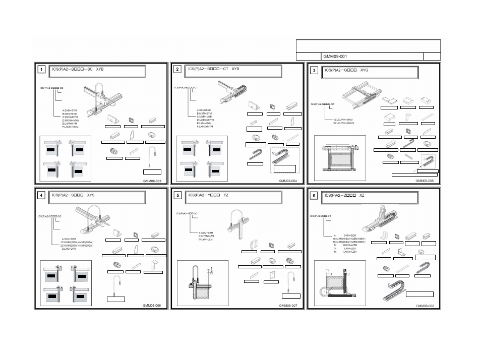
Drawing No.
ICS(P)A Cartesian Robot – Completed Drawings
(X-axis Base Mount)
Self-supporting Cable Specification
(Model)
(Model)
(Model)
(Model)
(Model)
(Model)
H: High speed
M: Medium speed
Configuration direction
X-axis Y-axis
H: High speed
M: Medium speed
Configuration direction
X-axis Y-axis
[Configuration directions]
[Assembled parts]
[Configuration directions]
[Assembled parts]
[Configuration directions]
[Assembled parts]
[Configuration directions]
[Assembled parts]
[Configuration directions]
[Assembled parts]
[Configuration directions]
[Assembled parts]
Type 1
Type 2
(Reverse of type 1)
Type 3
(Y-axis installed on
opposite side)
Type 4
(Reverse of type )
[1] X-Y bracket
[2] Box cover
[3] Connector box (small)
[4] Connector box (large)
[5] Bracket cover
[6] Grommet with film
[7] Cable fix cap
[8] Joint cover
[9] Self-supporting
cable assembly
[Assembly Procedure]
Drawing No.:
Type 1
Type 2
(Reverse of type 1)
Type 3
(Y-axis installed on
opposite side)
Type 4
(Reverse of type 3)
[1] X-Y bracket
[2] Box cover
[3] Connector box
[4] Box spacer,
BA type only
[5] Joint cover
[6] Bracket cover
[7] Grommet with film
(
30, 34)
[8] Cable fix cap
[9] Guide rail
[10] Cable track
[2], [3], [5] and [9] are
assembled before the
shipment.
[Assembly Procedure]
Drawing No.:
[Assembly Procedure]
Drawing No.:
[Assembly Procedure]
Drawing No.:
[Assembly Procedure]
Drawing No.:
[Assembly Procedure]
Drawing No.:
(Y-axis Base Mount)
Cable Track Specification
(Gantry) Type
Cable Track Specification
(Y-axis Slider Mount)
Self-supporting Cable Specification
(Y-axis Slider Mount)
(Z-axis Base Mount)
H: High speed
X-axis Y-axis
[1] X-Y bracket (1)
[2] X-Y bracket
[3] Pin bracket
[4] Spacer
[5] Mounting bracket
[6] Guide rail
[7] Connector box (small)
[8] Box cover
[9] Joint cover
[10] Connector box (large)
[11] Cable track
[12] Grommet with film
[13] Cable fix cap
[14] Packing frame
Cable track assembly
[5], [6] and [11] are assembled before the shipment.
H: High speed
M: Medium speed
Configuration direction
X-axis Y-axis
[1] X-Y bracket
[2] Box cover
[3] Connector box (small)
[4] Connector box (large)
[5] Bracket cover
[6] Grommet with film
[7] Cable fix cap
[8] Joint cover
[10] Self-supporting
cable assembly
[8] Mounting bracket
Combination
direction: 1
(Operation range)
Combination
direction: 2
(Reverse of 1)
(Operation range)
Combination
direction: 3
(Y-axis installed on
opposite side)
(Operation range)
Combination
direction: 4
(Reverse of 1)
(Operation range)
H: High speed
M: Medium speed
Y-axis Z-axis
[1] X-Y bracket
[2] Box cover
[3] Connector box (small)
[4] Connector box (large)
[5] Grommet with film
[6] Cable fix cap
[7] Joint cover
[8] Box spacer
[9] Self-supporting
cable assembly
H: High speed
M: Medium speed
X-
axis Y-axis
[1] X-Y bracket
[2] Box cover
[3] Connector
box (small)
[3] Connector
box (large)
[4] Joint cover
[5] Mounting bracket
[6] Grommet with film
(
30, 34)
[7] Cable fix cap
[8] Guide rail
[9] Cable track
[6], [9] and [10] are assembled
before the shipment.
1/9