IAI America ICS(P)A User Manual
Page 25
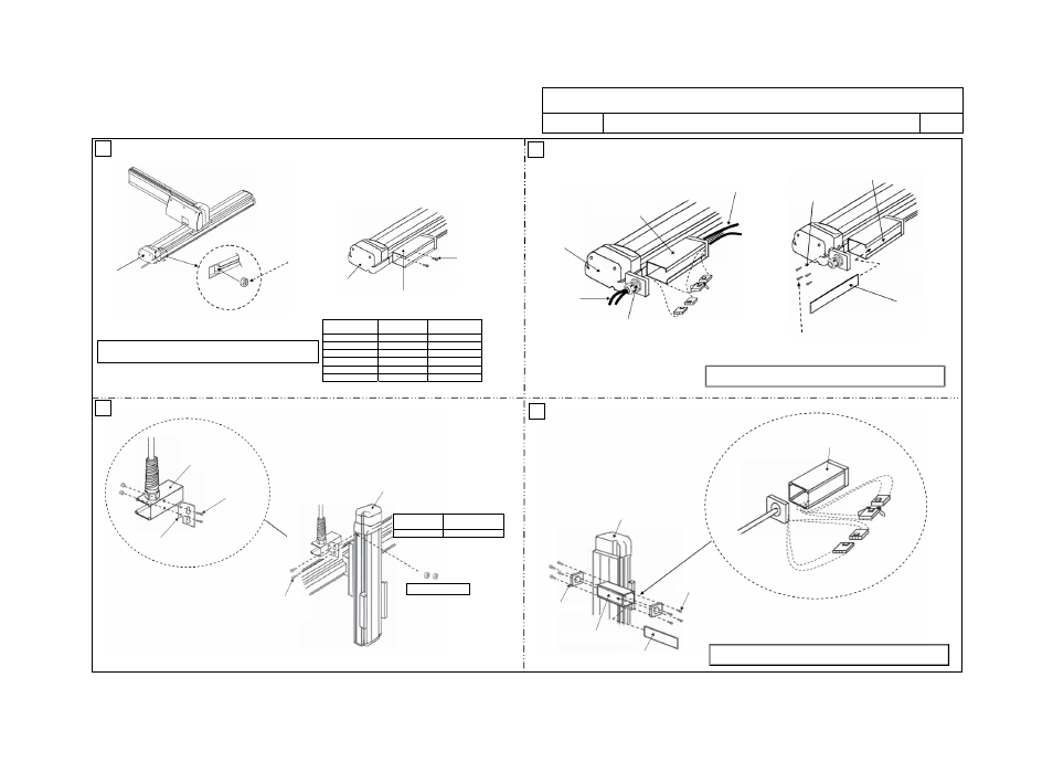
ICS(P)A Cartesian Robot, 3-axis Configuration X-Y Base Mount (XYB) + Z-axis (Z-axis Base Mount) Type
ICS(P)A3-B
B-CT-SC
X-axis/Y-axis: Cable Track, Y-axis/Z-axis: Self-supporting Cable
Drawing No.
GMM08-010
3/3
Hexagonal
socket head bolt
Tightening torque
M4x8mm 18kgf
xcm/176Nxcm
11
13
14
12
Configuration type
Hexagonal
socket head bolt
Tightening torque
ICS(P)A-BA M4x14mm
18kgf
xcm/176Nxcm
ICS(P)A-BB M4x6mm
18kgf
xcm/176Nxcm
ICS(P)A-BC M4x6mm
18kgf
xcm/176Nxcm
ICS(P)A-BD M4x6mm
18kgf
xcm/176Nxcm
ICS(P)A-BE M4x6mm
18kgf
xcm/176Nxcm
ICS(P)A-BF M4x6mm
18kgf
xcm/176Nxcm
M4 x 8 mm (2 pcs)
M3 x 12 mm (4 pcs)
X-axis: IS(P)A
M4 hexagonal nut
X-axis: IS(P)A
[3] Connector box
[5] Joint cover
[3] Connector box
X-axis: IS(P)A
[3] Connector box
X-axis: IS(P)A
Controller-actuator
cable
Cable inside cable track
[8] Cable fix cap
[10] Connector joint for cable
inside cable track and
controller-actuator cable
[5] Connector box (small)
Z-axis: ICS(P)A
[13] Box cover support
Insert two M4 nuts.
Flange-head hexagonal
socket head bolt
M4 x 8
[14] Connector joint for cable
inside cable track and
controller-actuator cable
Z-axis: ICS(P)A
[9] Box cover
[4] Connector box (medium)
[7] Joint cover (medium)
M3 x 12 mm (4 pcs)
Place two M4 hexagonal nuts in the slot provided on the side face of
the X-axis before the connector box [3] is installed.
BA: M4 x 14 mm (2 pcs)
+ spacer
BB to BF: M4 x 6 mm
(2 pcs)
[3] Connector box
[5] Connector box
(small)
Follow “Instruction for Cable Track Type Wiring (Drawing No. GMM12-001)”
for how to lay out the wiring inside a cable track.
Follow “Instruction for Cable Track Type Wiring (Drawing No. GMM12-001)”
for how to lay out the wiring inside a cable track.