IAI America ICS(P)A User Manual
Page 12
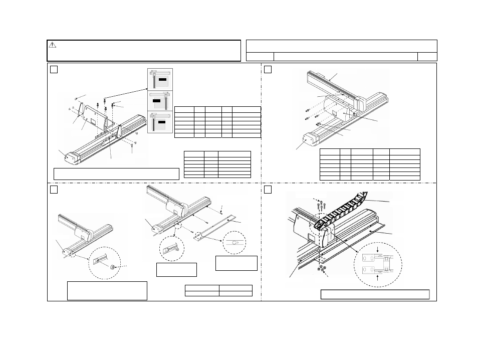
ICS(P)A Cartesian Robot, 2-axis Configuration XYB (Y-axis Base Mount) Type
ICS(P)A2-B
-CT Cable
Track
Caution:
x Although each part has been chamfered to remove sharp edges, exercise due caution
during the assembly to prevent injury. If necessary, wear gloves or other protective gears.
x Exercise due caution during the assembly to prevent pinching of hands and fingers.
Drawing No.
GMM08-004
1/2
* This assembly procedure applies to combination direction 1. If other combination direction such as 2, 3 or 4 is used, the actuator and bracket directions vary. However, you can still use this assembly drawing as a reference.
3
4
Flange-head hexagonal
socket head bolt
Tightening torque
M4x6mm 18kgf
xcm/176Nxcm
1
2
Configuration
type
Parallel
pin
Hexagonal
bolt
High-
tension
Tightening torque
ICS(P)A-BA
6x15
M6x30mm
M6 54.7kgf
xcm/536Nxcm
ICS(P)A-BB
8x18
M8x35mm
M8 306kgf
xcm/2997Nxcm
ICS(P)A-BC
8x18
M8x35mm
M8 306kgf
xcm/2997Nxcm
ICS(P)A-BD
8x18
M8x35mm
M8 306kgf
xcm/2997Nxcm
ICS(P)A-BE
8x18
M8x35mm
M8 306kgf
xcm/2997Nxcm
ICS(P)A-BF
8x18
M8x35mm
M8 306kgf
xcm/2997Nxcm
Configuration
type
Thin-head
screw
Tightening torque
ICS(P)A-BA
M3x6mm
8.9kgf
xcm/87.2Nxcm
ICS(P)A-BB
M3x6mm
8.9kgf
xcm/87.2Nxcm
ICS(P)A-BC
M4x6mm
20.8kgf
xcm/204Nxcm
ICS(P)A-BD
M4x6mm
20.8kgf
xcm/204Nxcm
ICS(P)A-BE
M4x6mm
20.8kgf
xcm/204Nxcm
ICS(P)A-BF
M4x6mm
20.8kgf
xcm/204Nxcm
Configuration
type
Parallel
pin
Hexagonal
socket head bolt
Dedicated
washer
Tightening torque
ICS(P)A-BA
6x15 M6x20mm Not
required
54.7kgf
xcm/536Nxcm
ICS(P)A-BB
6x15 M6x20mm Not
required
54.7kgf
xcm/536Nxcm
ICS(P)A-BC
8x18 M8x28mm Required
306kgf
xcm/2997Nxcm
ICS(P)A-BD
8x18 M8x28mm Required
306kgf
xcm/2997Nxcm
ICS(P)A-BE
8x18 M8x28mm Required
306kgf
xcm/2997Nxcm
ICS(P)A-BF
8x18 M8x28mm Required
306kgf
xcm/2997Nxcm
[Tools] Allen wrench
In the case of configuration direction types 2 to 4,
the actuator and bracket directions are different.
Thin-head screw (3 pcs)
[5] Bracket cover
[1] X-Y bracket
Thin-head screw (3 pcs)
Parallel pin (1 pc or 2 pcs)
Hexagonal socket
head bolt (4 pcs)
High-tension washer
Type 2
(Reverse of type 1)
Type 3
(Y-axis installed on
opposite side)
Type 4
(Reverse of type 3)
X-axis: IS(P)A
Note: To ensure squareness between the X-axis and Y-axis, insert one parallel pin.
Adjust the angle between the X-axis and Y-axis to the right angle, and then mount
the hexagonal bolts.
Y-axis: IS(P)A
[1] X-Y bracket
Parallel pin (2 pcs)
Dedicated washer
Hexagonal socket head bolt (4 pcs)
X-axis: IS(P)A
[Installation of Y-axis: IS(P)A on X-Y bracket [1]]
M6 x 8 mm (4 pcs)
[10] Cable track
[9] Guide rail
M6 hexagonal nut (4 pcs)
X-axis: IS(P)A
X-axis: IS(P)A
X-axis: IS(P)A
[9] Guide rail
The M4 hexagonal nut in the slot provided on the
side face of the X-axis, before the guide rail [9] is
installed. The number of hexagonal nuts to be
placed in the slot varies according to the stroke.
Install the bolts before
the guide rail [9] is
installed.
Install the bolts by
hooking them in the
holes in the guide rail [9].
[Installation of guide rail [9] on X-axis: IS(P)A]
M4 hexagonal nut
Flange-head hexagonal
socket head bolt
M4 x 6 mm
[Installation of X-Y bracket [1] on X-axis: IS(P)A]
[Installation of bracket cover [5] on X-Y bracket [1]]
Follow “Instruction for Cable Track Type Wiring (Drawing No. GMM12-001)”
for how to lay out the wiring inside a cable track.