Gilderfluke&Co old MACs 8 bit Digital Audio System User Manual
Page 61
If you have hooked up the Digital Audio Repeaters to your computer and it still doesnÕt seem to
respond to the keyboard, the first thing to check is that you are attached to the right serial port. The
easiest way to do this is to disconnect the Digital Audio Repeaters and short between the Tx data out
and Rx data in pins on the serial port connector on the back of your computer. On all IBMs and
compatibles this means sticking a paper clip or similar tool between pins 2 and 3 on the ÔCom.Õ
connector. While still running the modem program, anything you type should be shown on the screen
while this paper clip is in place, while nothing will appear when you remove it. If your computer passes
this test, then you are using the right serial port and the problem is most likely the baud rate setting or in
your wiring to the Digital Audio Repeaters. If you get characters on the screen even with the paper clip
removed from the serial port, it means you probably need to set the ÔechoÕ mode to ÔnoneÕ or Ôfull
duplexÕ and try this test again.
The serial data signals from the digital audio Repeaters are brought out on the back of the card
cage on the connector labeled 'DIGITAL DATA' (CC-400 and CC-1600). The signals can be found on the
following pins:
PIN #
SIGNAL NAME:
4
- SERIAL DATA OUT FROM REPEATER (BLACK)
6
+ SERIAL DATA OUT FROM REPEATERS (RED)
7
- SERIAL DATA IN TO REPEATERS (GREEN)
9
+ SERIAL DATA IN TO REPEATERS (YELLOW)
25
SIGNAL GROUND (WHITE or BLUE)
For AB-100 cards, a 6 position RJ-11 (modular telephone style connector) is used for the serial data.
Facing the end of the cable with the release latch upwards, its pin out is as follows:
COLOR
SIGNAL NAME:
LEFT
WHITE
SIGNAL GROUND
BLACK
- SERIAL DATA OUT FROM REPEATER
RED
+ SERIAL DATA OUT FROM REPEATERS
GREEN
- SERIAL DATA IN TO REPEATERS
YELLOW
+ SERIAL DATA IN TO REPEATERS
RIGHT
BLUE
SIGNAL GROUND
To cross wire the RS-422 / RS-485 signals from the digital audio system to the RS-232 serial port of an
IBM compatible, cross connect the signals as follows:
DB-25
DE-9
SIGNAL
SIGNAL FROM/TO AUDIO SYSTEM
2
3
DATA OUT
- SERIAL DATA IN TO REPEATERS (GREEN)
3
2
DATA IN
- SERIAL DATA OUT FROM REPEATER (BLACK)
7
5
GROUND
SIGNAL GROUND (BLUE or WHITE)
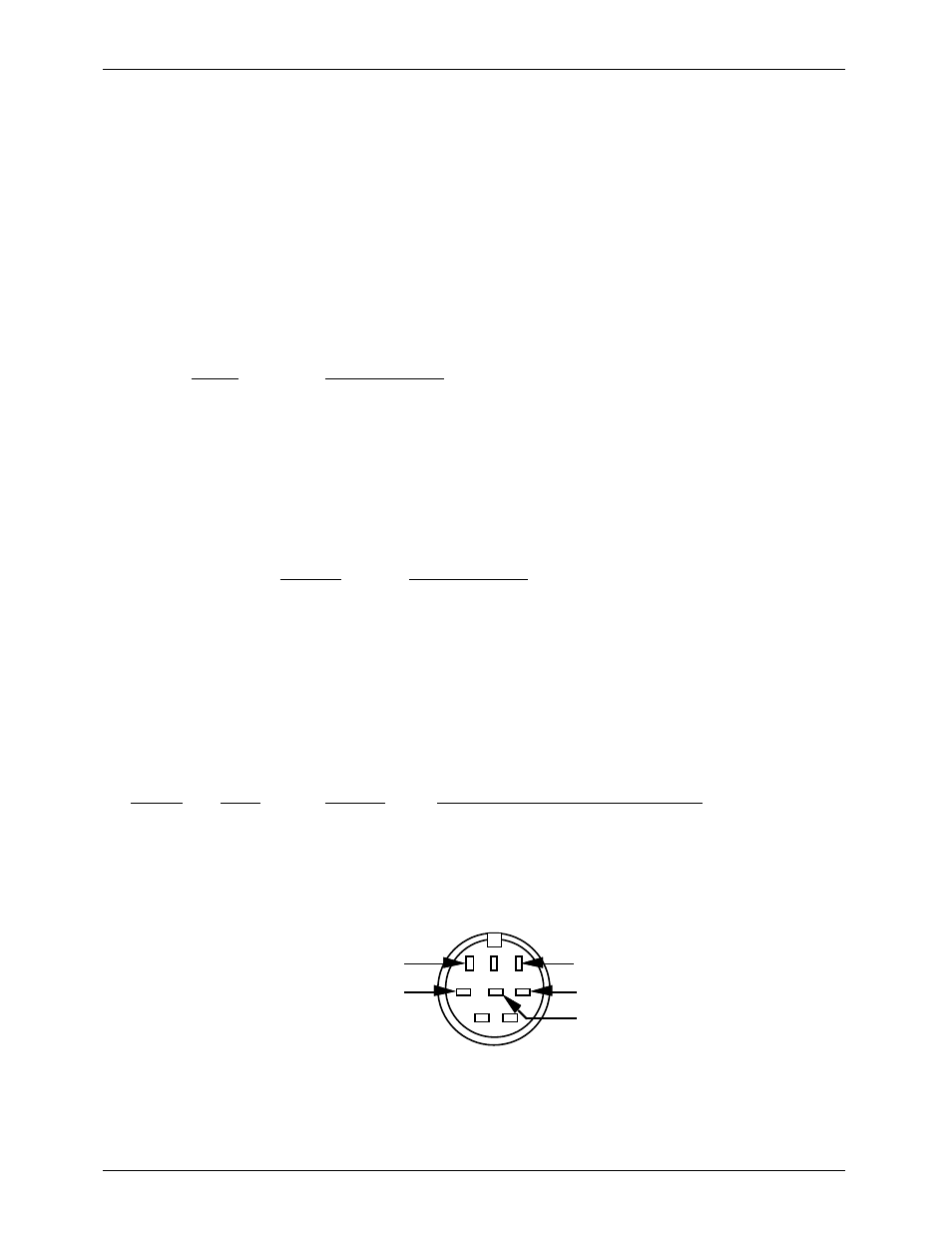
Apple Macintosh computers have true RS-422 serial ports built in. To connect to the digital audio sys-
tem, the pin out is as follows (view is of connector on the outside of a Macintosh):
to + serial data in to repeaters (yellow)
to - serial data in to repeaters (green)
1
2
3
4
5
6
7
8
from - serial data out from repeaters (black)
from + serial data out from repeaters (red)
signal ground (white or blue)
The digital audio system expects to see the serial data in the following format:
ONE START BIT
EIGHT DATA BITS
G
ILDERFLUKE
& C
o
. ¥ 205 S
OUTH
F
LOWER
S
T
. ¥ B
URBANK
, C
ALIF
. 91502-2102 ¥ 818/840-9484 ¥
FAX
818/840-9485
51