Vca buss dipswitch configuration, Global/mix buss dipswitch configuration, 18 i vca bus – Gilderfluke&Co old MACs 8 bit Digital Audio System User Manual
Page 42: 14 mix
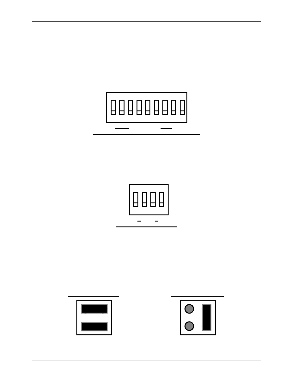
- VCA Buss Dipswitch Configuration -
A nine position dip switch is used to select what source will be used for the VCA (see the card block
diagrams). Switch positions 1 through 8 select any of the eight VCA Bus lines. Switch 9 is used if you
don't want or need to use the VCA functions. It feeds the 10 VDC reference level to the VCA circuits.
You then use the 'VOLUME' pot on the front panel to set the overall level of the card.
No more than one of these nine switches should be turned 'on' at a time or you will short together
the different VCA Bus lines. You can feed in a VCA control signal to an individual card through the
dedicated screw terminals on the back of the card cage. Normally you should leave all nine switches
'off' when you do this. However, if you want this signal to feed the VCA's of some additional cards, you
can turn on any one of the VCA Bus switches to feed it to a VCA Bus line.
1
2
3
4
5
6
7
8
ON
9
1
8 I
VCA BUS
¥¥¥¥¥¥¥¥¥¥¥¥¥¥¥¥¥¥¥¥¥¥¥¥¥¥¥¥¥¥¥¥¥¥¥¥¥¥¥¥¥¥¥¥¥¥¥¥¥¥¥¥¥¥¥¥¥¥¥¥¥¥¥¥¥¥¥¥¥¥¥¥¥¥¥¥¥¥¥¥¥¥¥¥¥¥¥¥¥¥¥¥¥¥¥¥¥¥¥¥¥¥¥¥¥¥¥¥¥¥¥¥¥¥¥¥¥¥¥
- Global/Mix Buss Dipswitch Configuration -
The GLOBAL / MIX BUS is configured by inserting one of six jumper modules in the socket near the
lower left corner of the Digital Audio Repeater / Mixer card. You can then select one, and only one of
the GLOBAL / MIX BUS lines by using the GLOBAL / MIX BUS SELECT SWITCH. (Instructions on full use of the
GLOBAL/MIX BUS can be found in another section in this manual.)
1
2
3
4
ON
1
4
MIX
If you are using the AUX INPUT rather than the GLOBAL / MIX BUS as a source or destination, you
should leave all four of the switches 'off'.
¥¥¥¥¥¥¥¥¥¥¥¥¥¥¥¥¥¥¥¥¥¥¥¥¥¥¥¥¥¥¥¥¥¥¥¥¥¥¥¥¥¥¥¥¥¥¥¥¥¥¥¥¥¥¥¥¥¥¥¥¥¥¥¥¥¥¥¥¥¥¥¥¥¥¥¥¥¥¥¥¥¥¥¥¥¥¥¥¥¥¥¥¥¥¥¥¥¥¥¥¥¥¥¥¥¥¥¥¥¥¥¥¥¥¥¥¥¥¥
- Repeater Start and Status Internal/External Power Jumper -
The Digital Audio Repeater START and STATUS signals are optically isolated from all other parts of the
system. You have the option of running them from the isolated power supply or from an external power
supply. JP-3 header is located in the upper right corner of the Digital Audio Repeater / Mixer card. It is
used to select which supply is used for these connections:
INTERNAL POWER
EXTERNAL POWER
G
ILDERFLUKE
& C
o
. ¥ 205 S
OUTH
F
LOWER
S
T
. ¥ B
URBANK
, C
ALIF
. 91502-2102 ¥ 818/840-9484 ¥
FAX
818/840-9485
32