Archive – Ransburg Evolver 202 Solvent A11918-XXX User Manual
Page 86
AA-07-01
8 1
8 1
8 1
8 1
8 1
Evolver 202 Robotic Atomizers - Parts Identification
79151-00
Needle Shaft
1
7723-06
Piston, U-Cup
1
79001-28
O-Ring, Solvent Proof
1
79001-29
O-Ring, Solvent Proof
1
13076-13
O-Ring, Teflon
1
RME-38
Spring
1
RME-32
Seal
1
79001-01
O-Ring, Solvent Proof
4
79001-04
O-Ring, Solvent Proof
1
79001-06
O-Ring, Solvent Proof
3
79001-05
O-Ring, Solvent Proof
1
A1041
A1041
A1041
A1041
A10411 SPRA
1 SPRA
1 SPRA
1 SPRA
1 SPRAY
Y
Y
Y
Y HEAD
HEAD
HEAD
HEAD
HEAD
REP
REP
REP
REP
REPAIR KIT
AIR KIT
AIR KIT
AIR KIT
AIR KIT
Part #
Part #
Part #
Part #
Part #
Description
Description
Description
Description
Description
Q t y
Q t y
Q t y
Q t y
Q t y
Figure 30: 77620-00 Valve Plug Assembly
Figure 30: 77620-00 Valve Plug Assembly
Figure 30: 77620-00 Valve Plug Assembly
Figure 30: 77620-00 Valve Plug Assembly
Figure 30: 77620-00 Valve Plug Assembly
Fluid Coils (Separate Sales
Fluid Coils (Separate Sales
Fluid Coils (Separate Sales
Fluid Coils (Separate Sales
Fluid Coils (Separate Sales
Parts Only)
Parts Only)
Parts Only)
Parts Only)
Parts Only)
If purchasing spare parts, they must be modified
as explained.
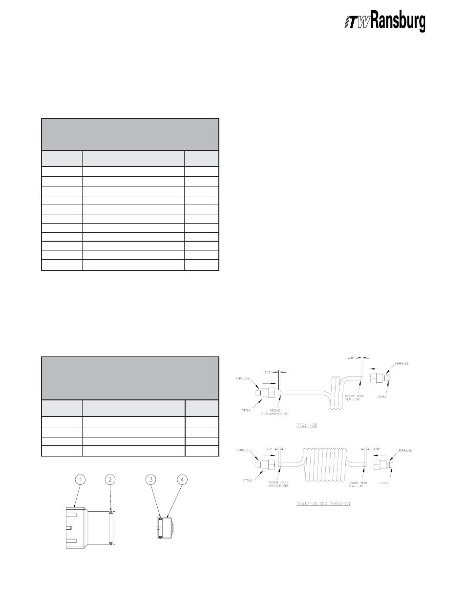
To ensure proper sealing and holding, the fittings
require that the ends of the Teflon fluid coils have
a groove cut into them as shown (see Figure 31).
Use groove cutter A11567-00 by sliding the end of
the tool over the Teflon tubing until it bottoms out.
Hold the tubing in one hand and the tool in the
other. Make three complete revolutions of the tool,
on the tubing, in the direction of the arrow stamped
on the tool. To remove the tool, hold the tube and
the main body of the tool with one hand, slide the
rear portion of the tool back until it stops. Pull out
the tubing from the end of the tool. By pulling back
the rear portion of the tool, it relieves the pressure
of the cutting edge off of the tubing before sliding it
out. Trim off ends to dimensions shown. End
should be cut off square. Slide the fitting and
ferrules onto the tube as shown. The tapered
ferrule must go past the newly cut groove to
properly lock into place when installed.
Tighten nuts into manifolds by hand until it stops.
Using a 9/16" end-wrench, tighten 1/4-1/2 turn.
Figure 31: Fluid Coils
Figure 31: Fluid Coils
Figure 31: Fluid Coils
Figure 31: Fluid Coils
Figure 31: Fluid Coils
79244-00
Plug
1
77618-00
Plug Seat
1
79001-19
O-Ring, Solvent Proof
1
79001-14
O-Ring, Solvent Proof
1
77620-00 V
77620-00 V
77620-00 V
77620-00 V
77620-00 VAL
AL
AL
AL
ALVE PLUG KIT
VE PLUG KIT
VE PLUG KIT
VE PLUG KIT
VE PLUG KIT
(((((Optional - Use In Place Of
Optional - Use In Place Of
Optional - Use In Place Of
Optional - Use In Place Of
Optional - Use In Place Of
V
V
V
V
Valve & Seat
alve & Seat
alve & Seat
alve & Seat
alve & Seat)))))
Part #
Part #
Part #
Part #
Part #
Description
Description
Description
Description
Description
Q t y
Q t y
Q t y
Q t y
Q t y
A1041
A1041
A1041
A1041
A10411-00
1-00
1-00
1-00
1-00 Spray Head Repair Kit
Spray Head Repair Kit
Spray Head Repair Kit
Spray Head Repair Kit
Spray Head Repair Kit
Available for purchase as a kit for the common
spray head parts that require replacement. This
kit contains parts for one applicator head.
77620-00 V
77620-00 V
77620-00 V
77620-00 V
77620-00 Valve Plug Kit
alve Plug Kit
alve Plug Kit
alve Plug Kit
alve Plug Kit
Available for purchase is a Valve Plug Kit than can
be used in place of valves and seats to convert the
applicator to a single purge applicator.
ARCHIVE