Archive, Spra – Ransburg Evolver 202 Solvent A11918-XXX User Manual
Page 27
AA-07-01
2 2
2 2
2 2
2 2
2 2
Evolver 202 Robotic Atomizers - Installation
SPRA
SPRA
SPRA
SPRA
SPRAY
Y
Y
Y
Y / BELL
/ BELL
/ BELL
/ BELL
/ BELL
APPLICA
APPLICA
APPLICA
APPLICA
APPLICAT
T
T
T
TOR
OR
OR
OR
OR
TRIGGERING
TRIGGERING
TRIGGERING
TRIGGERING
TRIGGERING
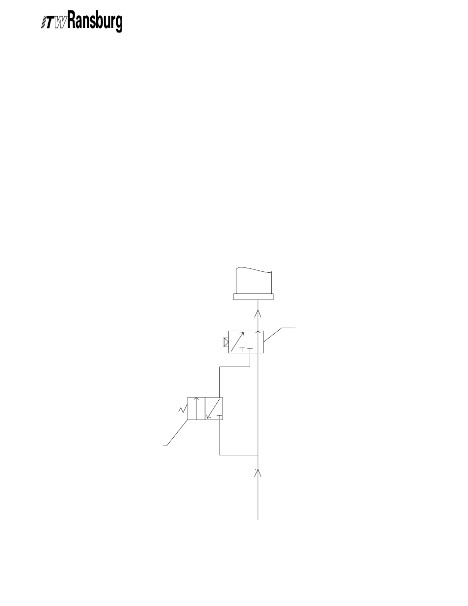
If you are currently using an RMA-202 bell
applicator system and want to add the Evolver 202
spray applicator system to spray using the same
tubing bundle, a simple conversion must be made
in order to allow for switching between spray and
bell applicators. Figure 7 shows the recommended
system that should be placed in the bearing air line
between the main air input and the robot manifold
plate. It is suggested that this circuit be placed on
the robot arm. This system should also be used
when the user is implementing the Evolver 202
spray applicator system and plans to use RMA-
202 bell applicators as well.
Figure 7: Conversion Schematic
Figure 7: Conversion Schematic
Figure 7: Conversion Schematic
Figure 7: Conversion Schematic
Figure 7: Conversion Schematic
In Figure 7, the trigger solenoid must be an
electronically activated, normally closed valve
with exhaust, or a 3-way valve, with 100 psi max.,
24VDC. Typically this solenoid already exists in
the robot arm and can be used in this circuit. The
spray applicator trigger/bearing air select valve
must be a pneumatically activated, normally open
solenoid. A suggested solenoid is ITW P/N 11678-
01. An additional solenoid must be used to activate
the P1T (Paint 1 Trigger) or P2T (Paint 2 Trigger)
valves. If any of these solenoids are located inside
a hazardous area, they must be explosion proof.
MAIN AIR LINE
SPRAY APPLICATOR SIDE
BELL APPLICATOR SIDE
TRIGGER
SOLENOID
SPRAY APPLICATOR TRIGGER/
BEARING AIR SELECT
BEARING AIR LINE
ARCHIVE