4 ethernet wiring (optional on d5 models only) – E-Mon E-D5-600800-S*SPL3-V3KIT3 User Manual
Page 31
DIN-MON™ SMART METER
31
62-0442—04
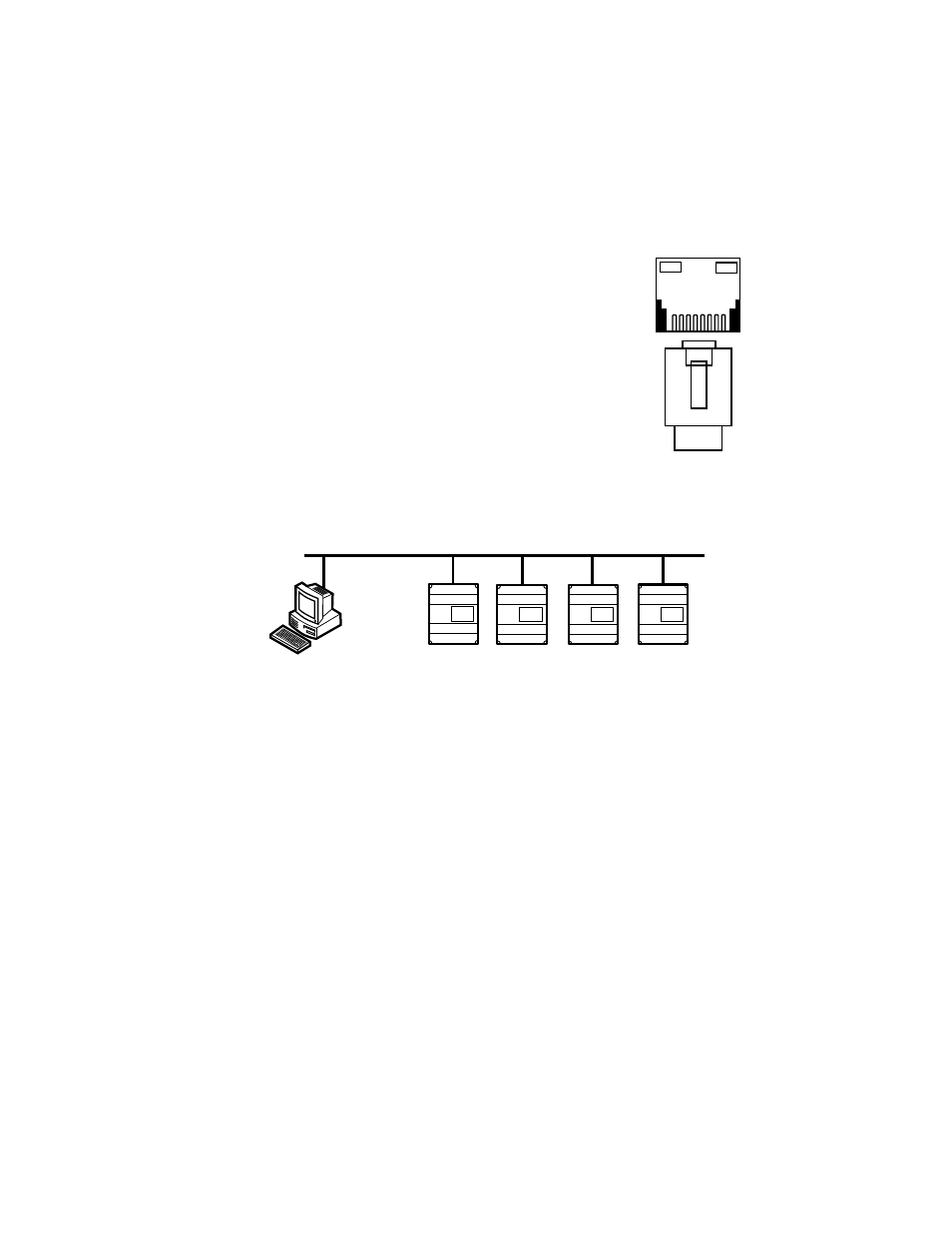
4.8.4 Ethernet Wiring (Optional on D5 Models Only)
Ethernet/IP communication connections are provided through an RJ-
45 connector on top of the meter. This port can be connected to a LAN
for use as an Intranet or Internet connection; or can be connected
directly to a network port of a PC using a Cat-5e crossover cable.
The Din-Mon™ Ethernet operates at 10/100-Base-T.
Two LEDs are provided directly above the connector. They are located
on the top of the modular jack. The LINK LED is yellow and when lit,
indicates Ethernet connectivity. The ACT LED is green and when lit,
indicates network communication activity.
The communication protocol for the Ethernet port is selected when
ordering the meter. The available choices are EZ7, Modbus TCP/IP,
and BACnet IP. See the ordering information section for the available
choices in combination with the RS-485.
Each device that is connected directly to the Ethernet network requires a unique IP
address.
Fig. 25. Ethernet Network
M35113
ETHERNET JACK
M35114
ETHERNET NETWORK
EMS OR CONTROL UNIT
- E-D5-600400-S*SPL3-V3KIT3 E-D5-600200-S*SPL3-V3KIT3 E-D5-600100-S*SPL3-V3KIT3 E-D5-480800-S*SPL3-V3KIT3 E-D5-480400-S*SPL3-V3KIT3 E-D5-480200-S*SPL3-V3KIT3 E-D5-480100-S*SPL3-V3KIT3 E-D2-400800-S*SPL3-V3KIT3 E-D2-400400-S*SPL3-V3KIT3 E-D2-400200-S*SPL3-V3KIT3 E-D5-400100-S*SPL3-V3KIT3 E-D5-208800-S*SPL3-V3KIT3 E-D5-208400-S*SPL3-V3KIT3 E-D5-208200-S*SPL3-V3KIT3 E-D5-208100-S*SPL3-V3KIT3 E-D2-600800-SEZ7SPL3-V3KIT3 E-D2-600400-SEZ7SPL3-V3KIT3 E-D2-600200-SEZ7SPL3-V3KIT3 E-D2-600100-SEZ7SPL3-V3KIT3 E-D2-480800-SEZ7SPL3-V3KIT3 E-D2-480400-SEZ7SPL3-V3KIT3 E-D2-480200-SEZ7SPL3-V3KIT3 E-D2-480100-SEZ7SPL3-V3KIT3 E-D2-400800-SEZ7SPL3-V3KIT3 E-D2-400400-SEZ7SPL3-V3KIT3 E-D2-400200-SEZ7SPL3-V3KIT3 E-D2-400100-SEZ7SPL3-V3KIT3 E-D2-208800-SEZ7SPL3-V3KIT3 E-D2-208400-SEZ7SPL3-V3KIT3 E-D2-208200-SEZ7SPL3-V3KIT3 E-D2-208100-SEZ7SPL3-V3KIT3