4 wiring the voltage, Warning – E-Mon E-D5-600800-S*SPL3-V3KIT3 User Manual
Page 17
DIN-MON™ SMART METER
17
62-0442—04
4.4 Wiring the Voltage
WARNING
High voltages are present on voltage input connections screw terminals.
Risk of serious injury and/or electrical shock exists. Prior to performing
any wiring operations, review all contents of the user manual and de-
energize the MAINS power switch. Only qualified personnel should
perform installation wiring. Installation wiring must comply with all local
and national electrical codes.
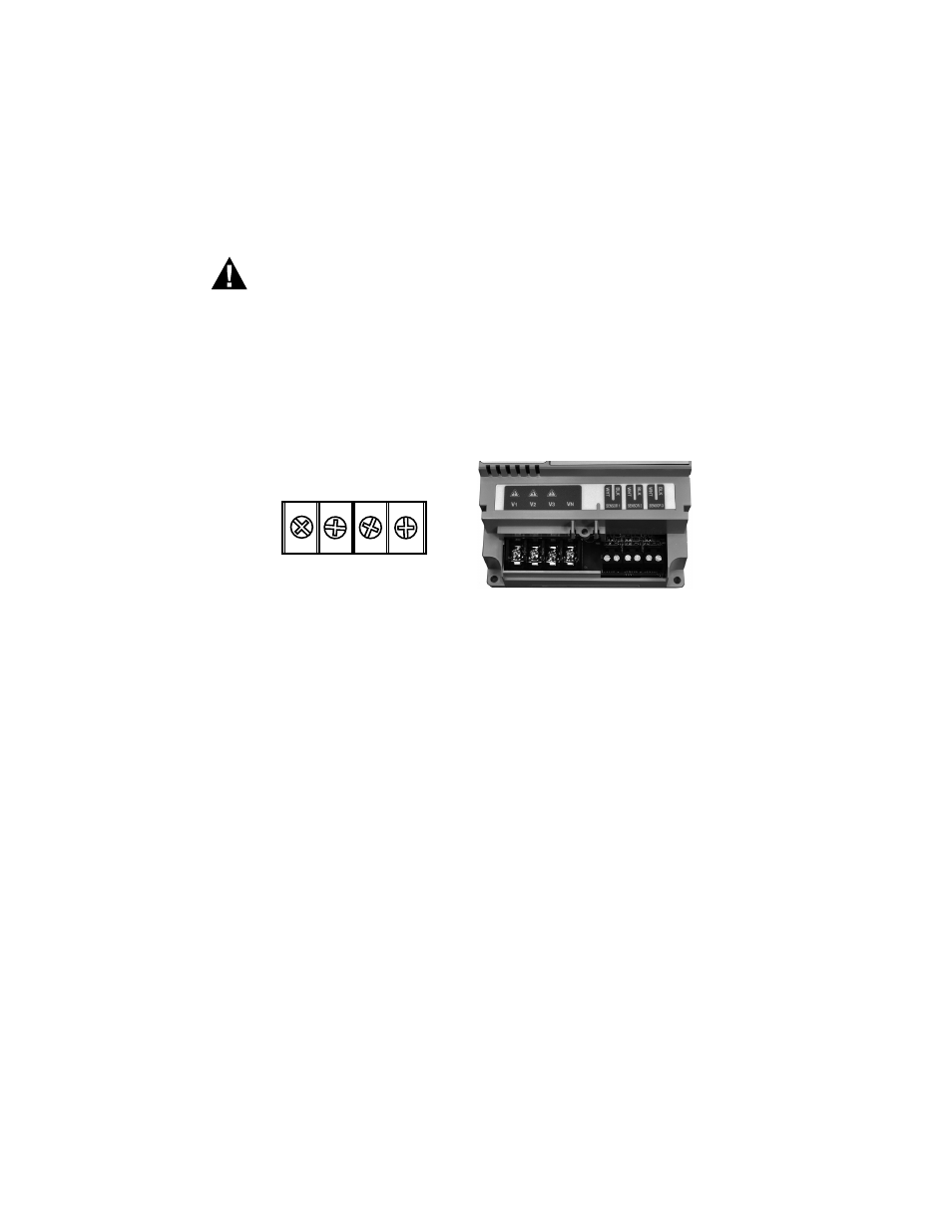
1. The four position terminal block located at the bottom left corner of the main
power board, is labeled V1, V2, V3, VN (neutral). Connect the NEUTRAL wire to
the appropriate terminal block position.
Fig. 12. Meter MAINS Voltage Input Terminal.
NOTE: For 3-wire delta-type applications, DO NOT connect the NEUTRAL wire.
Remove the terminal block screw for this position.
a. To ensure a safe installation, the Din-Mon™ meter requires an external
switch mechanism, such as a circuit breaker or in-line fuse, be installed on
the Din-Mon™ meter MAINS input wiring. The switch mechanism must be
installed in close proximity to the meter and easily reachable for the operator.
This device must also be marked as the disconnecting device for the Din-
Mon™ meter. Install 1/2 Amp fast activation in-line fuses with the suitable
voltage rating for each conductor phase at the MAINS input to the meter. The
fuses must be labeled to indicate voltage and current rating as well as ele-
ment characteristics. The fuse element must be a fast activating type, such
as the Littelfuse part number OKLK.500T (not included).
b. Connect the three AC main power wires (Phases A, B and C) to their respec-
tive positions on the 4-position terminal block and torque to 7 in-lb. Wiring
should be a minimum of #14 AWG, stranded, with 600V insulation rating.
After all conductors are connected to each of their respective terminal block
positions and tightened down, verify that each terminal block screw is
securely fastened by gently tugging on each conductor.
Verify that no conductor wires are frayed or shorting to adjacent terminal
block positions.
MAINS VOLTAGE INPUT
M35091
V
1
V
2
V
3
V
N
- E-D5-600400-S*SPL3-V3KIT3 E-D5-600200-S*SPL3-V3KIT3 E-D5-600100-S*SPL3-V3KIT3 E-D5-480800-S*SPL3-V3KIT3 E-D5-480400-S*SPL3-V3KIT3 E-D5-480200-S*SPL3-V3KIT3 E-D5-480100-S*SPL3-V3KIT3 E-D2-400800-S*SPL3-V3KIT3 E-D2-400400-S*SPL3-V3KIT3 E-D2-400200-S*SPL3-V3KIT3 E-D5-400100-S*SPL3-V3KIT3 E-D5-208800-S*SPL3-V3KIT3 E-D5-208400-S*SPL3-V3KIT3 E-D5-208200-S*SPL3-V3KIT3 E-D5-208100-S*SPL3-V3KIT3 E-D2-600800-SEZ7SPL3-V3KIT3 E-D2-600400-SEZ7SPL3-V3KIT3 E-D2-600200-SEZ7SPL3-V3KIT3 E-D2-600100-SEZ7SPL3-V3KIT3 E-D2-480800-SEZ7SPL3-V3KIT3 E-D2-480400-SEZ7SPL3-V3KIT3 E-D2-480200-SEZ7SPL3-V3KIT3 E-D2-480100-SEZ7SPL3-V3KIT3 E-D2-400800-SEZ7SPL3-V3KIT3 E-D2-400400-SEZ7SPL3-V3KIT3 E-D2-400200-SEZ7SPL3-V3KIT3 E-D2-400100-SEZ7SPL3-V3KIT3 E-D2-208800-SEZ7SPL3-V3KIT3 E-D2-208400-SEZ7SPL3-V3KIT3 E-D2-208200-SEZ7SPL3-V3KIT3 E-D2-208100-SEZ7SPL3-V3KIT3