2 installing solid-core current sensor – E-Mon E-D5-600800-S*SPL3-V3KIT3 User Manual
Page 22
DIN-MON™ SMART METER
62-0442—04
22
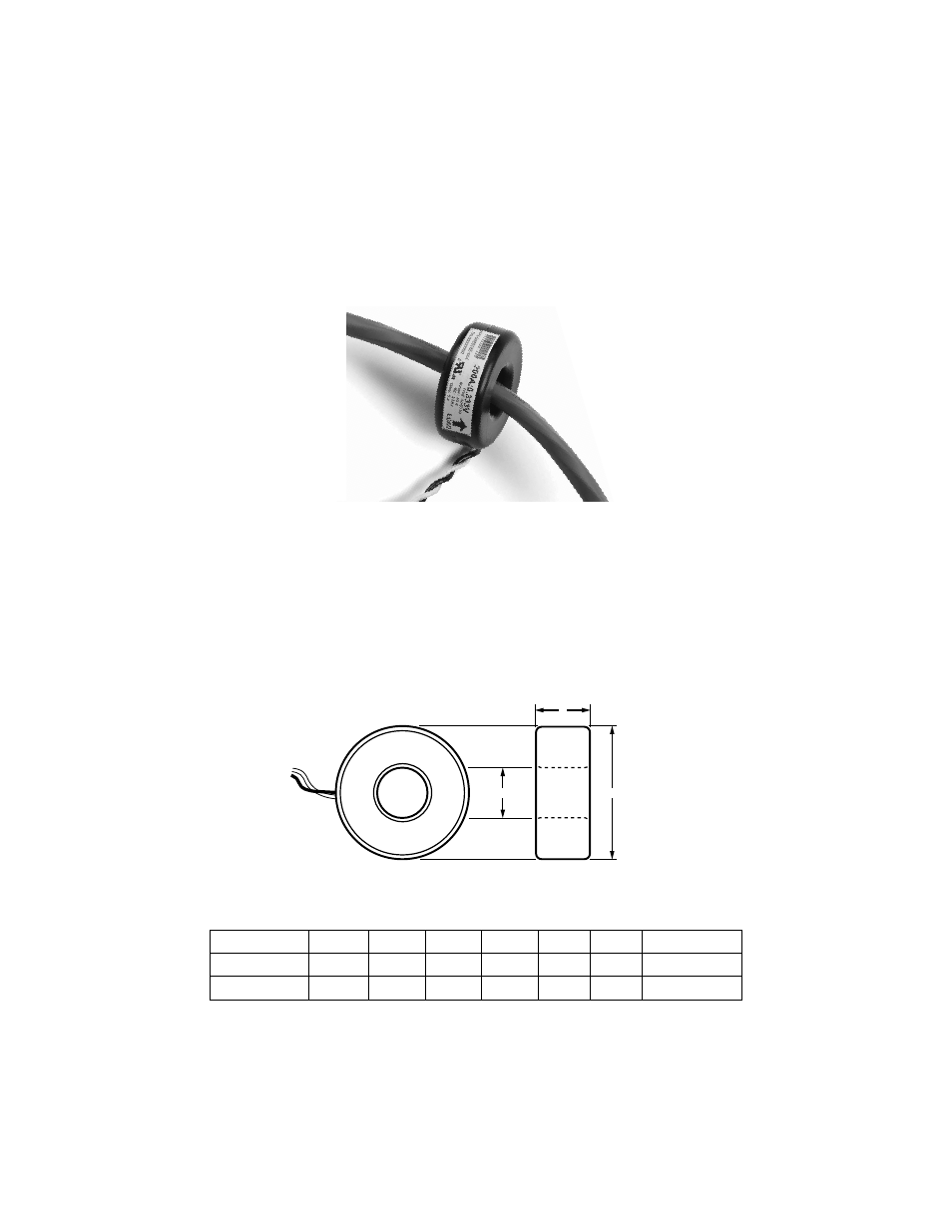
4.5.2 Installing Solid-Core Current Sensor
NOTE: Under no circumstances is this operation to take place without shutting
off the power to the conductor(s) being monitored.
Fig. 16. Typical Solid-Core Current Sensor.
1. With the power off, disconnect the conductor from its breaker or terminal.
2. Slide the solid-core current sensor over the conductor, making sure that the indi-
cator on the sensor is pointing in the direction of the load.
3. Reconnect the conductor.
4. Run the black and white wires from the current sensors to the meter and install
them according to the standard installation diagram.
Fig. 17. Split Current Sensor Dimensions.
P/N
AMPS
A
B
C
NOTE
50059386-003
100
2.00
0.80
0.75
50059386-004
200
2.00
0.80
0.75
LINE
SOURCE
LOAD
A
M35103
C
B
- E-D5-600400-S*SPL3-V3KIT3 E-D5-600200-S*SPL3-V3KIT3 E-D5-600100-S*SPL3-V3KIT3 E-D5-480800-S*SPL3-V3KIT3 E-D5-480400-S*SPL3-V3KIT3 E-D5-480200-S*SPL3-V3KIT3 E-D5-480100-S*SPL3-V3KIT3 E-D2-400800-S*SPL3-V3KIT3 E-D2-400400-S*SPL3-V3KIT3 E-D2-400200-S*SPL3-V3KIT3 E-D5-400100-S*SPL3-V3KIT3 E-D5-208800-S*SPL3-V3KIT3 E-D5-208400-S*SPL3-V3KIT3 E-D5-208200-S*SPL3-V3KIT3 E-D5-208100-S*SPL3-V3KIT3 E-D2-600800-SEZ7SPL3-V3KIT3 E-D2-600400-SEZ7SPL3-V3KIT3 E-D2-600200-SEZ7SPL3-V3KIT3 E-D2-600100-SEZ7SPL3-V3KIT3 E-D2-480800-SEZ7SPL3-V3KIT3 E-D2-480400-SEZ7SPL3-V3KIT3 E-D2-480200-SEZ7SPL3-V3KIT3 E-D2-480100-SEZ7SPL3-V3KIT3 E-D2-400800-SEZ7SPL3-V3KIT3 E-D2-400400-SEZ7SPL3-V3KIT3 E-D2-400200-SEZ7SPL3-V3KIT3 E-D2-400100-SEZ7SPL3-V3KIT3 E-D2-208800-SEZ7SPL3-V3KIT3 E-D2-208400-SEZ7SPL3-V3KIT3 E-D2-208200-SEZ7SPL3-V3KIT3 E-D2-208100-SEZ7SPL3-V3KIT3