6 main power & current sensor wiring diagram, 1 4-wire wye, 3-element connection diagram, 2 3-wire, 3-element connection diagram – E-Mon E-D5-600800-S*SPL3-V3KIT3 User Manual
Page 25: 3 3-wire, 2-element connection diagram
DIN-MON™ SMART METER
25
62-0442—04
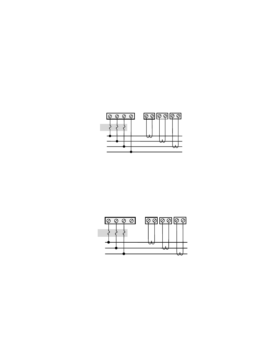
4.6 Main Power & Current Sensor Wiring Diagram
4.6.1 4-Wire Wye, 3-Element Connection Diagram
1. Recommended fuses or circuit breaker per the national electrical code (meter
load 6VA); refer to Technical Specification section.
2. Install current sensors according to instructions.
Fig. 19. 3-Phase, 4-Wire
(120/208V, 127/220V, 230/400V, 277/480V, 347/600V).
4.6.2 3-Wire, 3-Element Connection Diagram
1. Recommended fuses or circuit breaker per the national electrical code (meter
load 6VA).
2. Neutral MUST NOT be used in Delta system.
3. Install current sensors according to instructions.
Fig. 20. 3-Phase, 3-Wire (240V, 480V).
4.6.3 3-Wire, 2-Element Connection Diagram
1. Recommended fuses or circuit breaker per the national electrical code (meter
load 6VA).
2. Install jumper wire between V2 (ÆB) and V3 (ÆC).
3. Install current sensors according to instructions.
1/2 A
ØA
W B
SENSORS
1 2 3
MAINS
LOAD
SOURCE
WHITE
BLACK
WHITE
BLACK
WHITE
BLACK
W B
W B
ØB
ØC
N
V1 V2 V3 VN
M35105
1/2 A
ØA
W B
SENSORS
1 2 3
MAINS
LOAD
SOURCE
WHITE
BLACK
WHITE
BLACK
WHITE
BLACK
W B
W B
ØB
ØC
V1 V2 V3 VN
M35106
- E-D5-600400-S*SPL3-V3KIT3 E-D5-600200-S*SPL3-V3KIT3 E-D5-600100-S*SPL3-V3KIT3 E-D5-480800-S*SPL3-V3KIT3 E-D5-480400-S*SPL3-V3KIT3 E-D5-480200-S*SPL3-V3KIT3 E-D5-480100-S*SPL3-V3KIT3 E-D2-400800-S*SPL3-V3KIT3 E-D2-400400-S*SPL3-V3KIT3 E-D2-400200-S*SPL3-V3KIT3 E-D5-400100-S*SPL3-V3KIT3 E-D5-208800-S*SPL3-V3KIT3 E-D5-208400-S*SPL3-V3KIT3 E-D5-208200-S*SPL3-V3KIT3 E-D5-208100-S*SPL3-V3KIT3 E-D2-600800-SEZ7SPL3-V3KIT3 E-D2-600400-SEZ7SPL3-V3KIT3 E-D2-600200-SEZ7SPL3-V3KIT3 E-D2-600100-SEZ7SPL3-V3KIT3 E-D2-480800-SEZ7SPL3-V3KIT3 E-D2-480400-SEZ7SPL3-V3KIT3 E-D2-480200-SEZ7SPL3-V3KIT3 E-D2-480100-SEZ7SPL3-V3KIT3 E-D2-400800-SEZ7SPL3-V3KIT3 E-D2-400400-SEZ7SPL3-V3KIT3 E-D2-400200-SEZ7SPL3-V3KIT3 E-D2-400100-SEZ7SPL3-V3KIT3 E-D2-208800-SEZ7SPL3-V3KIT3 E-D2-208400-SEZ7SPL3-V3KIT3 E-D2-208200-SEZ7SPL3-V3KIT3 E-D2-208100-SEZ7SPL3-V3KIT3