1 installing split-core current sensor assembly – E-Mon E-D5-600800-S*SPL3-V3KIT3 User Manual
Page 21
DIN-MON™ SMART METER
21
62-0442—04
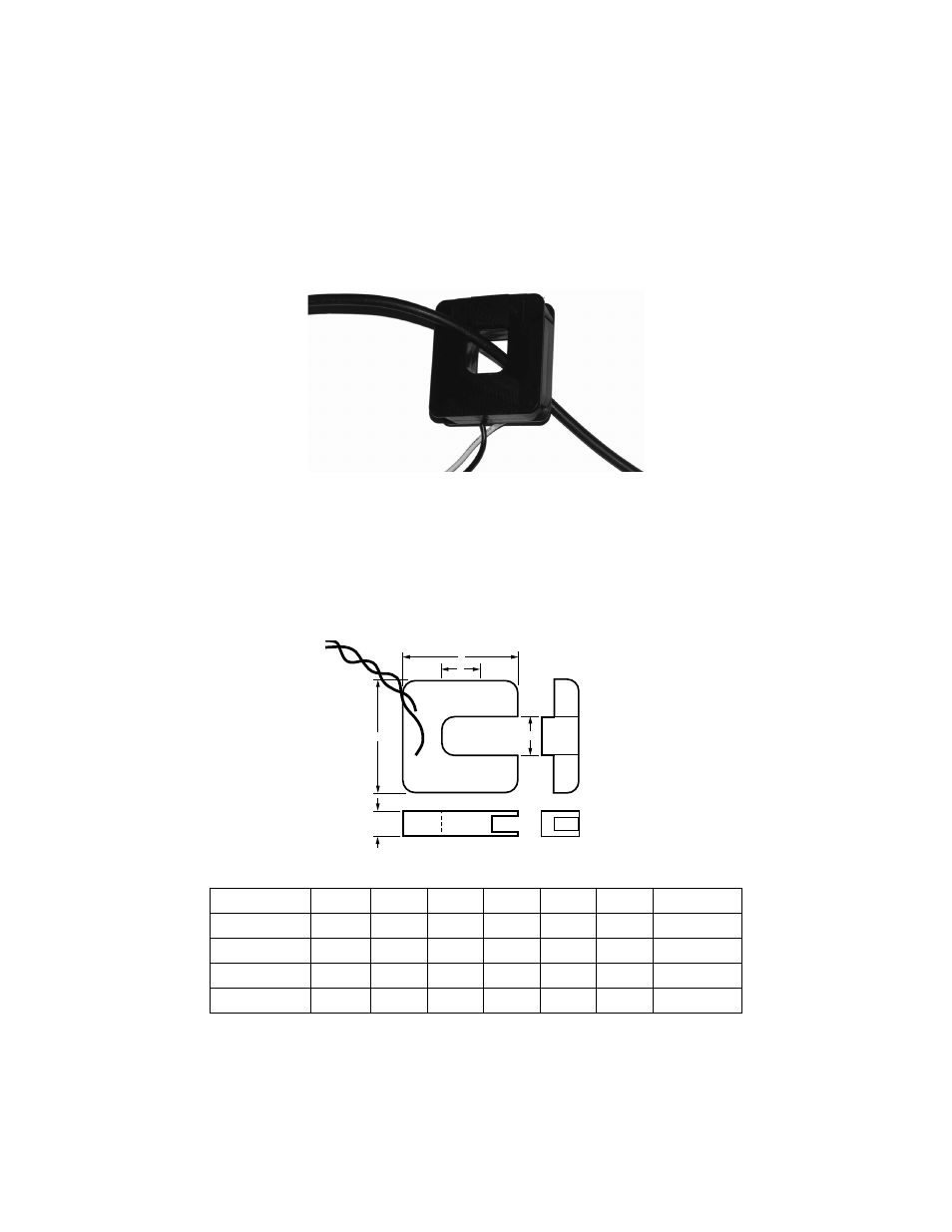
4.5.1 Installing Split-Core Current Sensor Assembly
1. Each phase being monitored will require one split-core current sensor assembly.
Open the current sensor assembly by lifting the top off the sensor.
Fig. 14. Typical Split Core Current Sensor.
2. Reassemble the current sensor assembly around the conductor(s) to be moni-
tored. Ensure the current sensor side marked “This Side Toward Source” is fac-
ing the source side of the metered conductor.
3. Run the Black and White wires from the current sensors to the meter and install
them according to the standard installation diagram.
Fig. 15. Split Current Sensor Dimensions.
P/N
AMPS
A
B
C
D
E
NOTE
50082281-006
100
2.00
2.10
0.60
0.75
0.75
50082281-008
200
3.25
3.35
1.00
1.25
1.25
50082281-010
400
3.25
3.35
1.00
1.25
1.25
50082281-012
800
4.75
5.00
1.20
2.00
2.00
M35137
SOURCE
LOAD
M35102
E
B
A
D
C
- E-D5-600400-S*SPL3-V3KIT3 E-D5-600200-S*SPL3-V3KIT3 E-D5-600100-S*SPL3-V3KIT3 E-D5-480800-S*SPL3-V3KIT3 E-D5-480400-S*SPL3-V3KIT3 E-D5-480200-S*SPL3-V3KIT3 E-D5-480100-S*SPL3-V3KIT3 E-D2-400800-S*SPL3-V3KIT3 E-D2-400400-S*SPL3-V3KIT3 E-D2-400200-S*SPL3-V3KIT3 E-D5-400100-S*SPL3-V3KIT3 E-D5-208800-S*SPL3-V3KIT3 E-D5-208400-S*SPL3-V3KIT3 E-D5-208200-S*SPL3-V3KIT3 E-D5-208100-S*SPL3-V3KIT3 E-D2-600800-SEZ7SPL3-V3KIT3 E-D2-600400-SEZ7SPL3-V3KIT3 E-D2-600200-SEZ7SPL3-V3KIT3 E-D2-600100-SEZ7SPL3-V3KIT3 E-D2-480800-SEZ7SPL3-V3KIT3 E-D2-480400-SEZ7SPL3-V3KIT3 E-D2-480200-SEZ7SPL3-V3KIT3 E-D2-480100-SEZ7SPL3-V3KIT3 E-D2-400800-SEZ7SPL3-V3KIT3 E-D2-400400-SEZ7SPL3-V3KIT3 E-D2-400200-SEZ7SPL3-V3KIT3 E-D2-400100-SEZ7SPL3-V3KIT3 E-D2-208800-SEZ7SPL3-V3KIT3 E-D2-208400-SEZ7SPL3-V3KIT3 E-D2-208200-SEZ7SPL3-V3KIT3 E-D2-208100-SEZ7SPL3-V3KIT3