Waveform marker concepts – Agilent Technologies E8267D PSG User Manual
Page 111
Chapter 3
97
Basic Digital Operation
Using Waveform Markers
There are three basic steps to using waveform markers:
“1. Clearing Marker Points from a Waveform Segment” on page 103
“2. Setting Marker Points in a Waveform Segment” on page 104
“3. Controlling Markers in a Waveform Sequence (Dual ARB Only)” on page 106
This section also provides the following information:
•
“Waveform Marker Concepts” on page 97
•
“Accessing Marker Utilities” on page 101
•
“Viewing Waveform Segment Markers” on page 102
•
“Viewing a Marker Pulse” on page 108
•
“Using the RF Blanking Marker Function” on page 109
•
“Setting Marker Polarity” on page 111
Waveform Marker Concepts
The signal generator’s ARB formats provide four waveform markers to mark specific points on a
waveform segment. You can set each marker’s polarity and marker points (on a single sample point
or over a range of sample points). Each marker can also perform ALC hold or RF Blanking and ALC
hold.
Marker File Generation
Generating a waveform segment (see
) automatically creates a marker file that places a
marker point on the first sample point of the segment for markers one and two.
Downloading a waveform file (as described in the Agilent Signal Generators Programming Guide)
that does not have a marker file associated with it creates a marker file that does not place any
marker points.
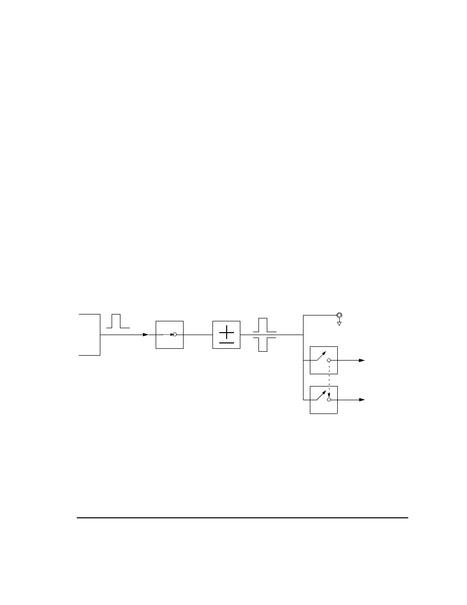
Marker
File
Bit N
Marker
Polarity
Marker N
RF Blank Off On
Marker N
Blanks RF
when Marker
is Low
EVENT N
Negative
Positive
Set Marker
On Off
Marker N
ALC Hold Off On
Marker N
Holds ALC
when Marker
is Low
When the signal generator encounters an enabled marker (described on
), an auxiliary output signal is generated and routed to the rear
panel event connector that corresponds to the marker number (N).
The EVENT 3 and 4 connectors are pins on the AUXILIARY I/O connector
(connector locations are shown in
).
RF Blank Only: includes ALC Hold