Trigger in, Source settled, Source module interface – Agilent Technologies E8267D PSG User Manual
Page 45
Chapter 1
31
Signal Generator Overview
Rear Panel
28. TRIGGER IN
This female BNC connector accepts a 3.3V CMOS signal, which is used for point–to–point triggering
in manual sweep mode, or in a low frequency (LF output) or analog (AM, FM, and
M) external
sweep trigger setup. Triggering can occur on either the positive or negative edge of the signal start.
The damage level is
4 V or 10 V. The nominal input impedance for this connector is
approximately 4.2 kohms.
29. SOURCE SETTLED
This female BNC connector provides a 3–volt CMOS output trigger, indicating when the signal
generator has settled to a new frequency or power level. A high indicates that the source has not
settled. A low indicates that the source has settled. The nominal output impedance for this connector
is less than 10 ohms.
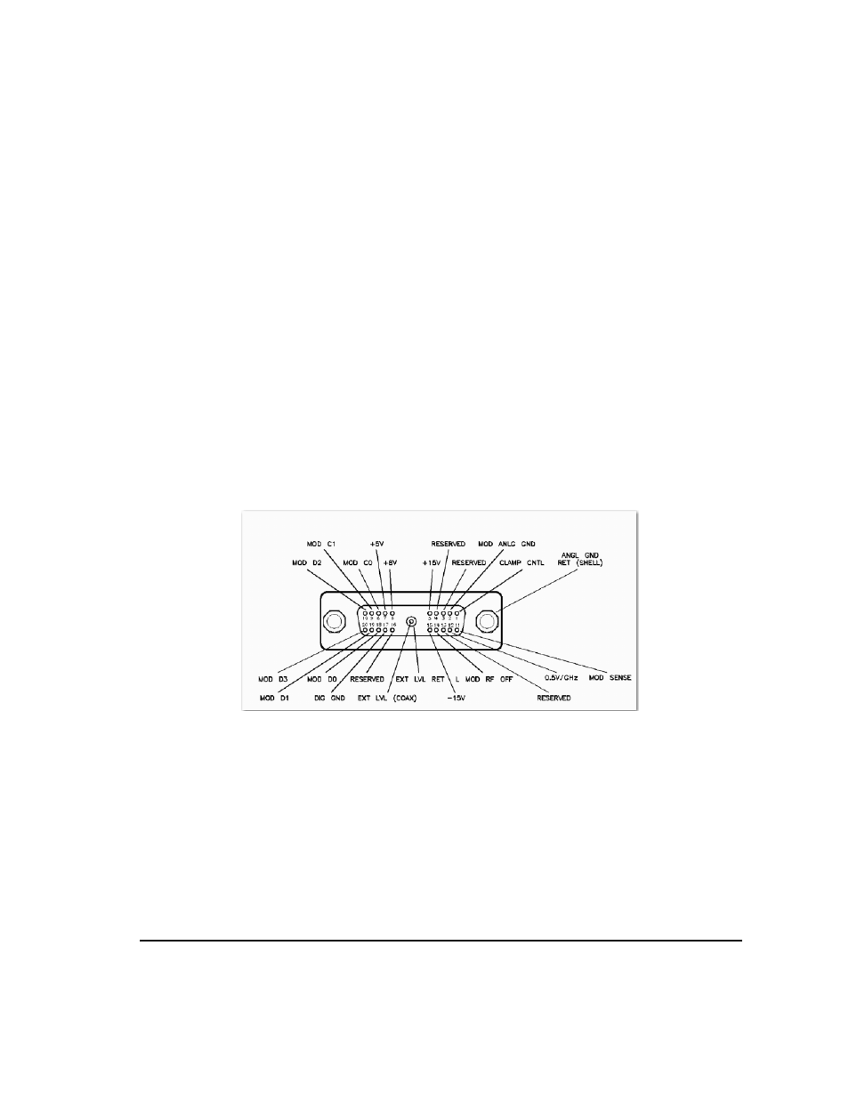
30. SOURCE MODULE INTERFACE
This interface is used to connect to compatible Agilent Technologies 83550 Series mm–wave source
modules.
Figure 1-9
Interface Signals of the Source Module Connector
The codes indicated on the illustration above translate as follows.
Mod D0
Source module data line zero. Signals MOD D0 through MOD D3 are the mm
source module data bus lines (bi- directional).
MOD D1
Data line one.
MOD D2
Data line two.
MOD D3
Data line three.
MOD C1
Source module control line zero. Signals MOD C0 and MOD C1 are the control
lines for the read/write to and from the mm source module.
MOD C1
Control line one.
CLAMP CNTL
Source module clamp control (not used).