3 configuring the database modules, Table 4-2. database modules – Micromod Micro-DCI: 53IT5100A Indicator/Totalizer User Manual
Page 45
4.3 CONFIGURING THE DATABASE MODULES
The datapoints in the database modules must be changed to reflect required alterations in the fac-
tory standard configuration or when the instrument is re-configured. There are generally four data-
point parameter types contained in the eight database modules. The parameter types affect
Datalink communications, display indications, input-output signals, and alarm conditions. The
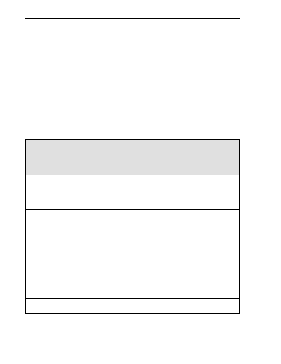
eight database modules are described in Table 4-2. Although it is not an absolute criterion, it is as-
sumed the modules will be configured in the table Item order; however, if the instrument is to be
connected to a Datalink network, item 7, Communication Module, should be configured first. By
configuring the Communication Module first, the instrument can function on the Datalink and the re-
maining datapoint values can be entered via the Datalink interrogator (master). Reference the ap-
plicable instruction bulletin (e.g., IB 53HC3300, IB53WS5000, or IB 53SU5000) for the procedure.
Table 4-2 is also a pointer to the descriptions of the database modules; the descriptions are pre-
sented as Tables 4-3 through 4-10. (The gray tone shading in the default cell of a datapoint indi-
cates the datapoint contents are left unchanged after default. See Section 5.5 for the default
procedure.)
Table 4-2. Database Modules
Item
Title
Purpose
See
Table
1
Analog Input Module
This module is used to configure the voltage input
characteristics (e.g., input voltage range) and how the input
signal is interpreted (linear or square root representation).
4-3
2
Analog Output
Module
The primary purpose of this module is to set the 0 - 20 mA
output signal relative to the displayed percent output.
4-4
3
Contact Input Module This module allows the action of the CCIs to be reversed
(normally a closed contact = 1, but can be change to = 0).
4-5
4
Contact Output
Module
This module allows the action of a CCOs to be reversed
(normally a closed contact = 1, but can be changed to = 0).
4-6
5
Alarm Module
The primary purpose of this module is to set the
instrument’s Alarm Index mode, Alarm Limits 1 & 2, and
Alarm Dead Band.
4-7
6
Totalizer Module
The totalizers provide the sum of each analog input (ANI0-
3). This module is used to set input scaling factors, rollover
and dropout values, and to define display tags for each
totalizer.
4-8
7
Communication
Module
This module is used to configure the Datalink port
parameters (e.g., baud rate, parity selection, etc.).
4-9
8
System Module
This module is used to set the instrument tag name and the
display brightness.
4-10
53IT5100 Indicator/Totalizer
4-2