0 displays & pushbuttons, 1 the six operator displays, 0 displays and push buttons – Micromod Micro-DCI: 53IT5100A Indicator/Totalizer User Manual
Page 28
3.0 DISPLAYS AND PUSH BUTTONS
This section provides illustrations with item call-outs of the six operator displays, alarm overlays,
and engineering mode overlays. Where applicable, datapoints are identified parenthetically with
the display item call-outs. The datapoints are defined in Section 4. The front panel push button
definitions are repeated in this section from Section 1, because they are used in the engineering
mode display overlay examples to enter a key password, display a datapoint, and alter a datapoint.
Hand Held Configurer operating procedures, which are an alternative to datapoint entries via the
front panel push buttons, are described last in the section.
3.1 THE SIX OPERATOR DISPLAYS
The Quad Bar Graph (Chs. 1-4), Dual Bar Graph (Chs. 1&2), Dual Bar Graph (Chs. 3&4), Quad
Process Digital Readout, Quad Totalizer Digital Readout, and Alarm Summary operator displays
are illustrated in Figures 3-1 through 3-6 respectively.
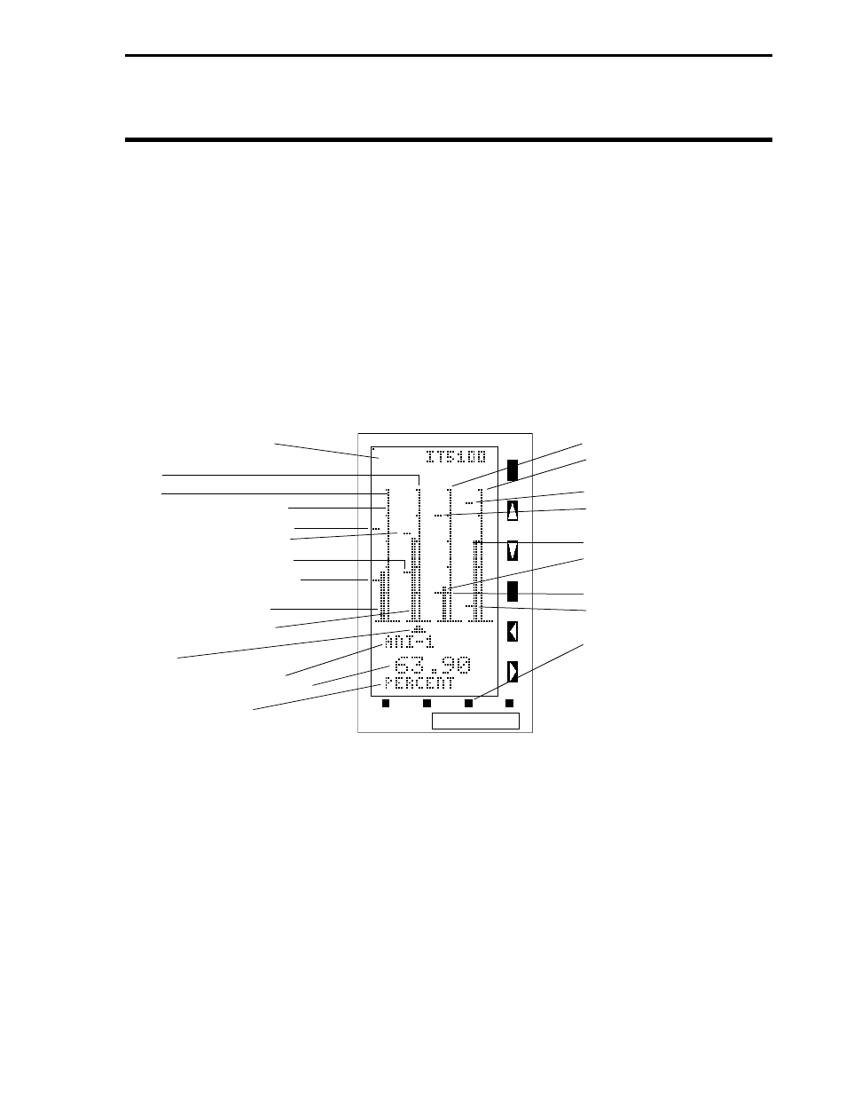
Figure 3-1. Quad Bar Graph (Channels 1-4)
Unit Tag Name (A008)
ANI1
ANI0
50 Segment Graph Scale
ANI0 Alarm Limit 1 (C103)
ANI1 Alarm Limit 1(C139)
ANI1 Alarm Limit 2 (C140)
ANI0 Alarm Limit 2 (C104)
ANI0 Process Variable
ANI1 Process Variable
Pointer
ANI-1 Tag Name (A225)
ANI1 Digital Readout (H001)*
ANI1 Units (A299)
*Display only.
ANI2
ANI3
ANI3 Alarm Limit 1 (C211)
ANI2 Alarm Limit 1 (C175)
ANI3 Process Variable
ANI2 Process Variable
ANI2 Alarm Limit 2 (C176)
ANI3 Alarm Limit 2 (C212)
Push Button 3 moves
Pointer to right when
pressed.
Alarm Index 0-3 and Alarm Dead Band 0-3 must also
be configured:
ANI0 Alarm Index (B335) ANI0 Dead Band (C105)
ANI1 Alarm Index (B340) ANI1 Dead Band (C141)
ANI2 Alarm Index (B345) ANI2 Dead Band (C177)
ANI3 Alarm Index (B350) ANI3 Dead Band (C213)
Section 3. Displays and Push Buttons
3-1