Micromod Micro-DCI: 53IT5100A Indicator/Totalizer User Manual
Page 10
Directly beneath the horizontal keypad and concealed behind the front panel pull-down door is the
RS-232 Configuration Port. This port provides instrument access to the database for alternative
methods, other than using the front panel push buttons in engineering mode, to input selections
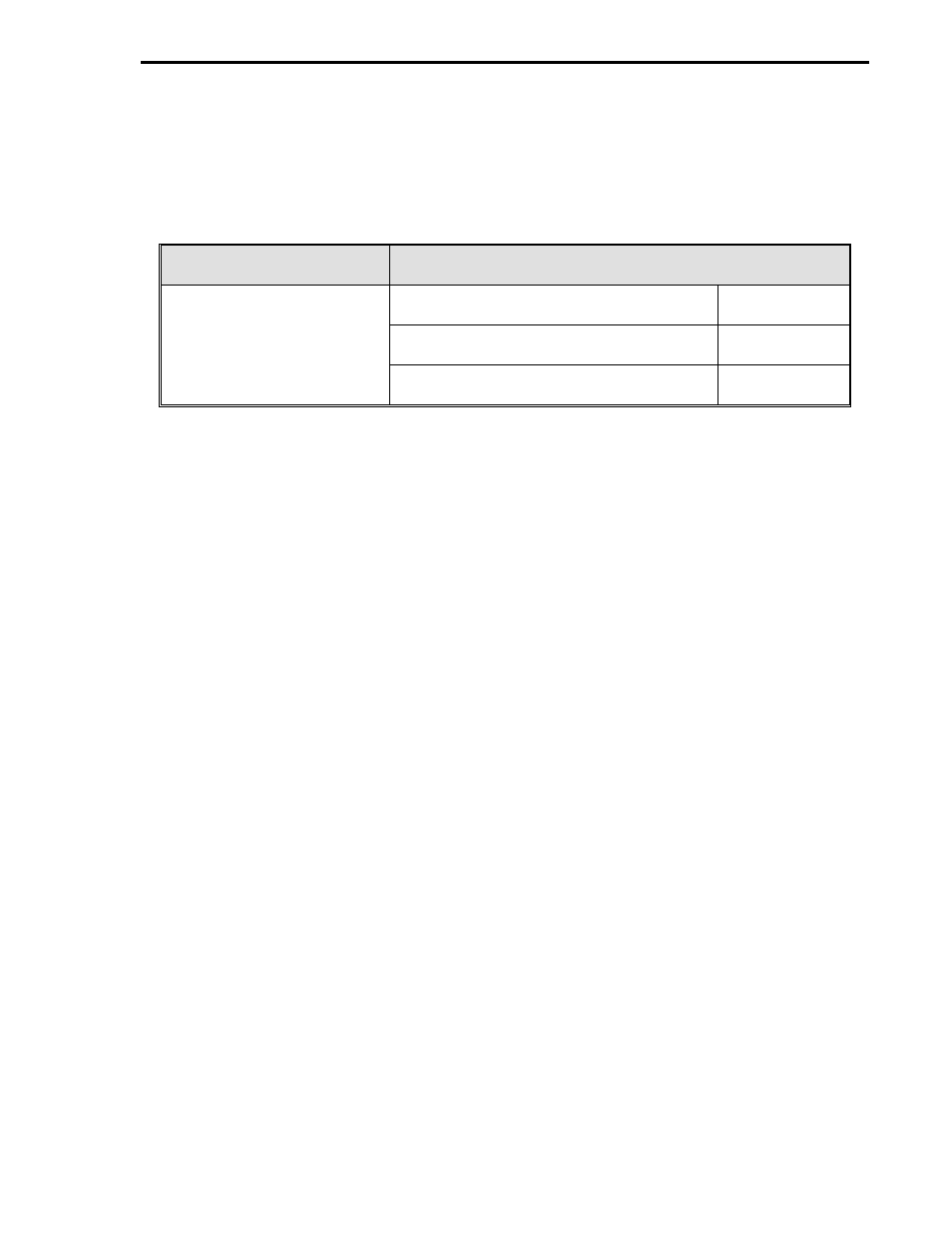
into the database for the operator displays. Alternative methods for loading or altering the instru-
ment database are summarized as follows:
Hand Held Configurer
(Procedure in Section 3)
Products on an IBM PC Compatible
Software/Hardware Package Reference
P/N 6988182U01 or
53HC3300 software package using
MC5FIG.EXE configuration program.
IB 53HC3300
P/N 6988182U02 with storage
cartridge capabilities.
53WS5000 software package using the
configuration program.
IB 53WS5000
Datalink SUPERVISOR-PC hardware and
software package.
IB 53SU5000
At the opposite end of the instrument case from the configuration port is the rear terminal board
which has two pin socket terminal strips (TB1 and TB2). As illustrated in Figure 1-2, the connec-
tors can be removed from the terminal strips to facilitate easier signal and power wiring when the
instrument is being installed. To ensure proper mating, only one side of the strips and connectors
is scalloped and the connectors are keyed. Also, as a further precaution, the signal connectors
that mate with the 22 pin terminal strip (TB1) are not the same size, as one has 12 screw lugs and
the other has 10 screw lugs.
Within the instrument case is the internal power supply. The internal power supply provides
power to the main board and output power for transmitters (24-26 V dc, 80 mA total available out-
put for instrument and transmitters).
Also within the instrument case is the main printed circuit board which has the necessary cir-
cuitry, firmware, and database for Indicator/Totalizer functionality. The main board has an embed-
ded microcontroller Application Specific Integrated Circuit (ASIC) that is surface mounted. The
PROM element and individual components are through-hole mounted.
A simplified input/output diagram of the Indicator/Totalizer is provided in the upper left corner of
Figure 1-2. As illustrated in the figure, the instrument can accept four Analog Inputs (ANI0-3 )
which are digitized as operands for firmware interpretation and execution (totalization). Each ANI
has a square root extractor and can accept linear or squared signals of 0-20 mA, 0-5 V, 4-20 mA,
or 1-5 V. Any one of the four analog inputs can be selected as the Analog Output (ANO0 ).
There are two contact inputs (CCI0 and CCI1 ) that have a closed recognition level of 1 V dc and
open recognition level of 4-24 V dc. Each CCI indicates an alarm state, for example, a CCI can
have a closed recognition level when a secondary pump is activated to support the primary pump
in maintaining a proper tank level.
The totalizers provide a running total of each ANI input. The totalizers are incremented in ascend-
ing order every 0.05 seconds, but all four totalizers are refreshed on the display every second.
Each ANI value can be independently adjusted by a scaling factor before being summed to the run-
ning total. The totalizer measured units, therefore, can differ from the process activity measured
units as determined by the scaling factor entries for each channel. Also available as selectable to-
talizer entries are rollover and dropout values. The rollover value specifies a maximum positive
value that causes the totalizer accumulator to reset to zero when the actual total reaches this
value. An output pulse is strobed to a 1 for one scan each time the actual total reaches the
Section 1. Introduction
1-5