0 configuration parameters, 1 datapoint types, 2 factory standard configuration – Micromod Micro-DCI: 53IT5100A Indicator/Totalizer User Manual
Page 44: Table 4-1. datapoint types
4.0 CONFIGURATION PARAMETERS
The configuration parameters provide the latitude to define the instrument’s personality attributes,
so that while still functioning within its designed specifications, it can perform application require-
ments with greater refinement. Typical configuration parameters are the instrument’s indicator
zero point and span, the display tag names, engineering units of the displayed process value, and
alarm limits, etc. IT IS NOT NECESSARY TO DEFINE ALL OF THE CONFIGURATION PARAME-
TERS, as commonly used preset values may not have to be altered and certain parameter selec-
tions eliminate others.
Although all resident in a memory database as datapoints, the configuration parameters are clus-
tered into modular groups that may have specific hardware identities (e.g., the ANI, ANO, CCI, and
CCO circuits illustrated in Figures 4-1 through 4-4), or may represent software controlled functions
that are not specific to any one hardware element.
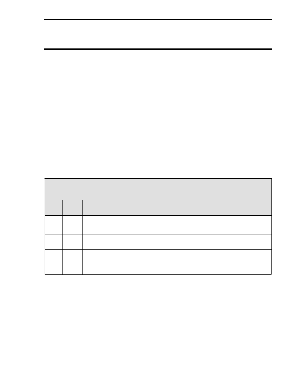
4.1 DATAPOINT TYPES
A parameter can be any one of five data types. Each data type represents a specific data format:
integers, alphanumeric text strings, etc. A database module containing multiple parameters can
have a mix of data types. The data types are defined in Table 4-1 as follows:
Table 4-1. Datapoint Types
Type
Byte
Size
Format
L
1 Bit
Represents a single binary bit that can have the value of 0 or 1.
B
1
Represents a positive integer with values from 0 to 255.
C
3
Represents a real analog (floating point) value that has a resolution of one part
in 32,768 (15 bits) and a dynamic range of
±
10
38
.
H
5
Represents a high precision analog (floating point) value that has a resolution of
one part in 2 billion (31 bits) and a dynamic range of
±
10
38
.
A
10
Represents a text string that can be 10 characters long.
4.2 FACTORY STANDARD CONFIGURATION
The instrument is shipped from the factory configured with all of the parameters set to the default
values. The default values are listed in the parameter tables under the heading Default. The
gray-tone shading in a default cell of a parameter indicates the contents of the datapoint are left un-
changed after the database is returned to the default condition using the procedure described in
Section 5.5. Examples of datapoints unaltered by default are the Calibrate Zero and Calibrate
Span parameters which are factory set.
Section 4. Configuration Parameters
4-1