Luminex 100 IS Version 2.3 User Manual
Page 187
x
MAP Technology
Luminex 100 IS System Setup
PN 89-00002-00-072 Rev. C
B - 5
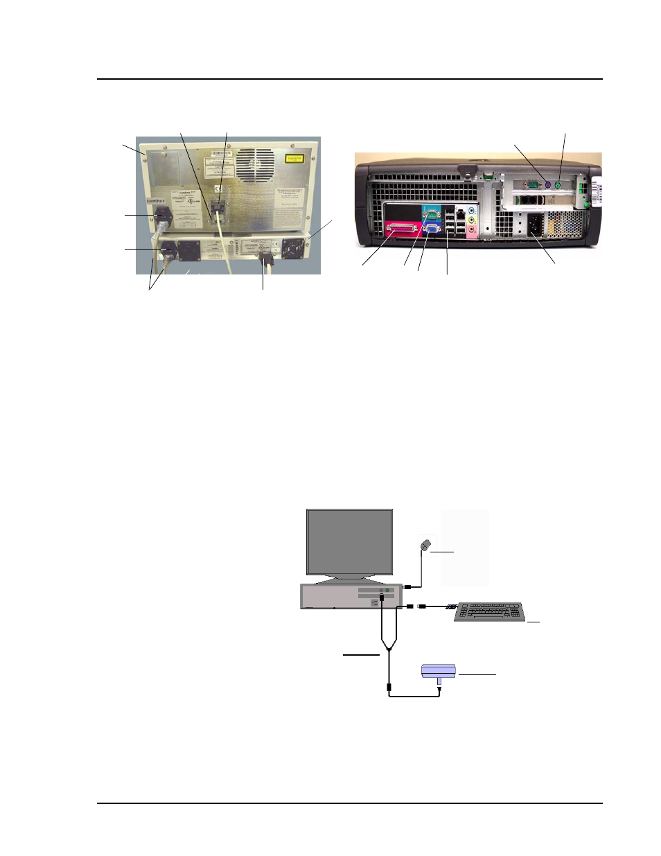
Figure B-4 Luminex 100 IS Connections (Luminex 100 analyzer, Luminex XYP Instrument, and PC)
11. Connect the Y-cable to the barcode reader and keyboard, then
connect the Y-cable to the PC. See Figure B-5.
Figure B-5 Connecting the PC, Mouse, Barcode Reader, and Keyboard
12
14
4
3
7
2
6
5
1
13
10
11
15
9
8
1. USB Communication Cable (P1)
9. Y-Cable Port
2. Luminex XYP Instrument
10. Mouse Cable port
3. Luminex XYP Instrument to PC Serial Cable
11.PC Power Cable
4. Power Cords
12. Luminex 100 port (USB)
5. Luminex XYP Instrument Power Switch
13. Monitor cable port
6. Luminex 100 Analyzer Power Switch
14. Luminex XYP port
7. Luminex 100 analyzer
15. Printer cable port
8. SD Cable (P2)
1
2
3
4
1. Keyboard
3. Y-Cable
2. Barcode Reader
4. Mouse