Traffic light speed bump hazard stripes, Separate pedestrian walkway, Non-contact sensor – Controlled Products Systems Group 1603-080 User Manual
Page 7: Contact sensor, Spike warning and illumination, Speed limit sign, Warning signs, Down loop, Stop
1603-065-T-4-13
5
SPEED
LIMIT
5
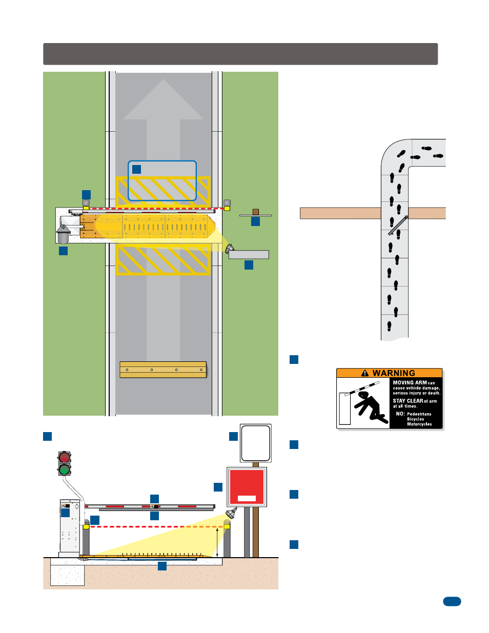
Safety Information for Vertical Barrier Arm and Spikes
Traffic Light
Speed Bump
Hazard Stripes
E
B
D
F
E
G
C
G
Helps increase distance
and time between vehicles.
No stopping or standing zone.
Permanently painted on pavement
and easily visible.
Separate
Pedestrian
Walkway
Located so pedestrians
cannot come in contact
with the barrier arm.
Non-Contact Sensor
C
Minimizes the potential of the arm lowering on
vehicular or other traffic that loops cannot sense.
Contact Sensor
D
Minimizes the potential of the arm lowering on
vehicular or other traffic that loops cannot sense.
Spike Warning and Illumination
E
It is extremely important that traffic spikes are
installed in an area that is illuminated and clearly
marked with spike warning signs (DoorKing’s
model 1615 illuminated warning sign kits).
Speed Limit Sign
F
Warning Signs
B
Permanently
mounted and
easily visible.
Helps control traffic.
Down Loop
A
Minimizes the potential of the
arm closing when a vehicle is
present. Number and
placement of loop(s) is
dependent on the application.
MOVING ARM
can
cause vehicle damage,
serious injury or death.
STAY CLEAR
of arm
at all times.
NO: Pedestrians
Bicycles
Motorcycles
WARNING
MOVING ARM
can
cause vehicle damage,
serious injury or death.
STAY CLEAR
of arm
at all times.
NO: Pedestrians
Bicycles
Motorcycles
WARNING
Helps control traffic.
STOP
SEVERE TIRE
DAMAGE
NO PEDESTRIANS
IN TRAFFIC LANE
PROCEED ONLY WHEN
SPIKES ARE DOWN
Photo Beam no higher than 27.5” above grade.
21” is typical for most installations.
B
C
A