This gate operator must be properly grounded – Controlled Products Systems Group 1603-080 User Manual
Page 11
1603-065-T-4-13
9
2.1 High Voltage Wire Runs
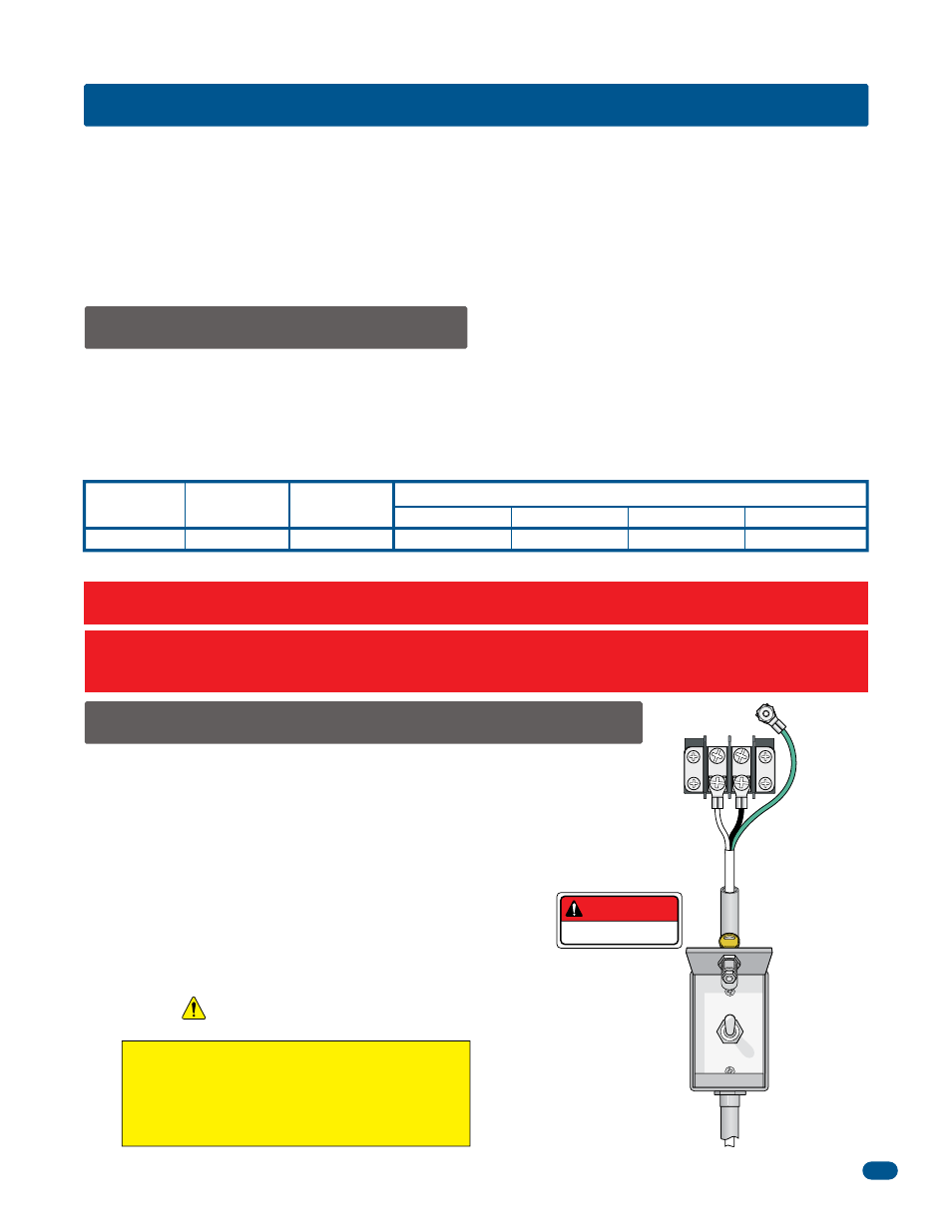
2.2 High Voltage Terminal Connections
This table illustrates the high voltage AC power wire size and distance limitations.
Model
Type
Voltage
Required
Amps
Required
Wire Size / Max Distance in Feet
115
5.7
12 AWG
10 AWG
8 AWG
6 AWG
1603 1/2 HP
SECTION 2 - WIRING
Before attempting to connect any wiring to the operator, be sure that the circuit breaker in the electrical panel is in the OFF
position. Permanent wiring must be installed to the operator as required by local electrical codes. It is recommended that a
licensed electrical contractor perform this work.
Since building codes vary from city to city, we highly recommend that you check with your local building department prior
to installing any permanent wiring to be sure that all wiring to the operator (both high and low voltage) complies with local
code requirements.
THIS GATE OPERATOR MUST BE PROPERLY GROUNDED!!
The distance shown in the chart is measured in “Feet” from the operator to the power source. If power wiring is greater than
the maximum distance shown, it is recommended that a service feeder be installed. When large gauge wire is used, a separate
junction box must be installed for the operator connection. The wire table is based on stranded copper wire. Wire run calcula-
tions are based on the NEC recommended maximum 3% voltage drop on the power line, plus an additional 10% reduction in
distance to allow for other losses in the system.
Never run low voltage rated wire insulation in the same conduit as high voltage rated wire insulation.
•
Route incoming high voltage power in it’s OWN conduit.
•
Be sure wiring is installed in accordance with local codes.
Be sure to color code all wiring.
•
It is recommended that a surge suppressor be installed on
the high voltage power lines to help protect the operator
and circuit board from surges and power fluctuations.
•
Dual operators (Primary/Secondary) require AC power to
each
operator.
Keep wire clear of all moving parts.
DO NOT
power up and cycle the operator until
the “DIP-Switches” have been set for the 1603
model (See pages 21 and 22).
The operator will not function properly unless the
switches have been correctly set.
“Optional” Heater Installation Note: When installing a heater, refer to the “high voltage AC power wire size
and distance limitations” table on the instruction sheet with the heater kit for AC power wire run limitations.
170
275
460
690
“Optional” High Voltage Kit Installation Note: When installing the high voltage kit for 208/230/460/575 VAC input power,
refer to the “high voltage AC power wire size and distance limitations” table on the instruction sheet with the
high voltage kit (P/N 2600-266) for AC power wire run limitations.
DANGER
HIGH VOLTAGE!
Chassis
Ground
Hot
Neu
White - Neutral
Black - 115 VAC Hot
Green - Chassis Ground
Note: A separate power disconnect
switch may be needed in your area. Check
local building codes before installation.
Note: “Optional”
High Voltage Kit
black and white wires
connect the same as
shown above.
High Voltage
AC Power Wire
External Power
Disconnect
Switch
AC POWER
ON
OFF
115 VAC
AC Power Terminal