3 dip-switch settings 7.2 dc system description, Switch function setting description, Arm rotation assembly in up position – Controlled Products Systems Group 1603-080 User Manual
Page 30
1603-065-T-4-13
28
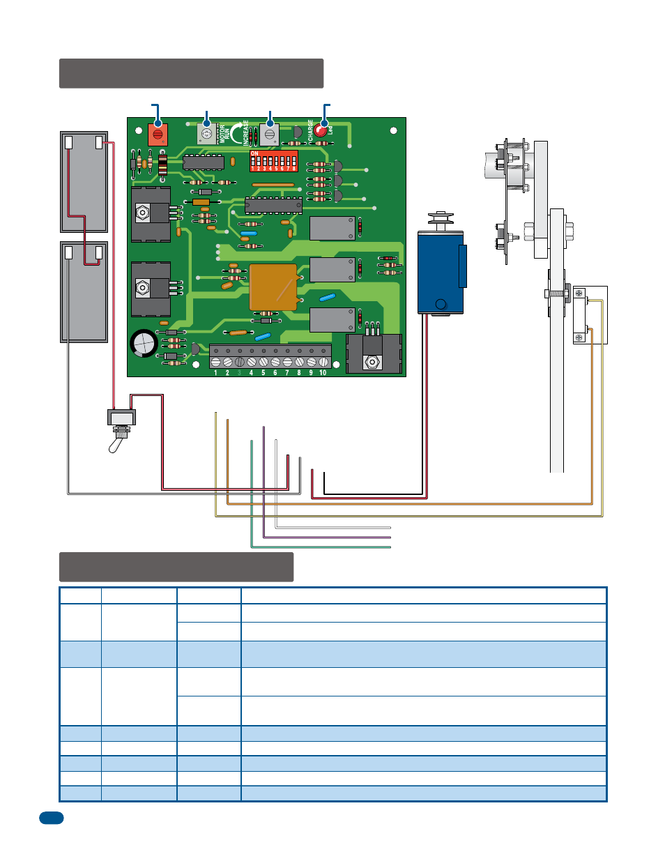
7.3 DIP-Switch Settings
7.2 DC System Description
Switch Function
Setting
Description
Operation
Changes
Open Direction
Automatic
Power-up
Activation
OFF
ON
ON
OFF
OFF
OFF
OFF
Operator Type
Not Used
Not Used
Not Used
Do Not Adjust
Do Not Adjust
Timer Not Used
Charging LED
Orange
Yellow
Not Used
Not Used
1
2
3
4
5
6
7
8
Arm will automatically open when a power outage occurs.
Set so that the arm runs to the open (up) direction upon loss of AC power.
OFF
ON
OFF
When AC power is restored, an input (push button, loop, radio receiver, etc.) is
required to return the arm to normal operation.
When AC power is restored, a 1-second pulse is sent to the gate operator input to
automatically restore normal operation.
Must be in the ON position.
2340
DIP-Switches
DC Magnet
Limit Assembly
(Adjusted at Factory)
Arm Rotation Assembly
in UP Position
DC Limit
Sensor
Arm will cycle to UP
position automatically
during an AC power
failure. DC limit sensor
will hold the arm in
the UP position.
DIP-Switch 3 setting
will determine how
arm will return to
normal operation once
AC power has been
restored.
–
+
12 V
3 Amp/Hr
–
+
12 V
3 Amp/Hr
Batteries
DC ON/OFF
Power Switch
Red
Black
DC Motor
Green to Main Terminal #8
White to Main Terminal #14
Red/White
Red/White
Red
Black/White
Purple to Main Terminal #5
DC Motor Negative Output
DC Motor Positive Output
Batter
y Negative Input
Batter
y Positive Input
24 V
AC Common
24 V
AC Input
Activation Output
Radio Power Not used.
Open Input
Common