4 control wiring for single/primary operator – Controlled Products Systems Group 1603-080 User Manual
Page 13
1603-065-T-4-13
11
CLASS
CERTIFIED TO
CAN/CSA C22.2 NO. 247
CONFORMS TO
ANSI/UL-325
VEHICULAR GATE OPERATOR
HP
53382
MODEL
SERIAL
VOLTS
PHASE
AMPS
60 Hz
MAX GATE LOAD
DoorKing, Inc., Inglewood, CA
MOVING ARM
can
cause vehicle damage,
serious injury or death.
STAY CLEAR
of arm
at all times.
NO: Pedestrians
Bicycles
Motorcycles
WARNING
Com
REVERSE
SENSITIVITY
TIME
DELAY
POWER
1
ON
2
3
4
5
6
7
8
1
ON
2
3
4
5
6
7
8
NC NO
UP
LOOP
DOWN
LOOP
1 2 3 4
5 6
7
8 9
10 11 12 13
14
1601
Non-Contact Sensor (Photo Sensors)
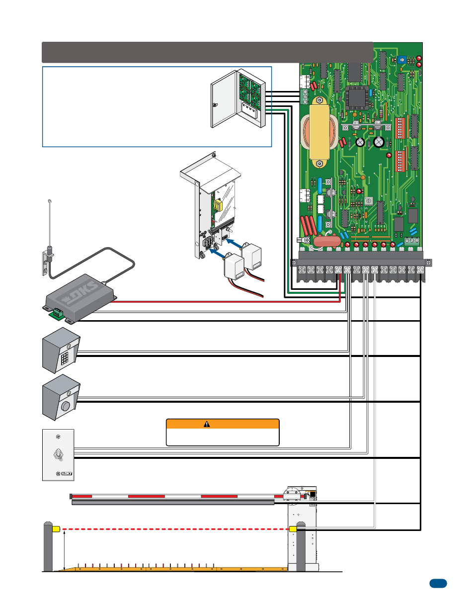
2.4 Control Wiring for Single/Primary Operator
1. Com
3. 24 Volt
2. Relay
3-Wire Radio Receiver
Up-Inputs
Down-Inputs
Manual Gate Control Toggle
P/N 1200-017
Up toggle position: User toggles switch up to hold gate open.
Center toggle position: Is neutral for normal operation.
Down toggle position: User momentarily toggles switch down to open gate.
User MUST make sure gate area IS CLEAR
before manually operating gate arm.
OPEN
HOLD OPEN
WARNING
Coax Antenna Kit
P/N 1514-073
Antenna mounted outside
operator housing.
21” Typical Beam Height.
27.5” Max. Beam Height.
Contact and Non-Contact Sensors Note:
Helps minimizes the potential of the arm
lowering on vehicular or other traffic that
loops cannot sense.
Contact Sensor (Reversing Edge)
See page 29
DoorKing Access Control System (Model 1833, 1835, 1837 or
1838) tracker system can be connected.
This system can keep track of gate operator cycle count, shorted
inputs, loop detector problems, any forced entry attempts, if the
gate has struck anything during the open or close cycle, power
interruptions, etc.
For more detailed information refer to the Tracker Installation and
Wiring Manual, DoorKing P/N 2351-010.
Terminal 6 required only if the tracker board will activate the gate
operator. Refer to the manual 2351-065 for detailed information.
Gat
e
Tracker
(Quad Box
Shown)
RE
VE
RSE
SEN
SITIVITY
TIM
E
DELA
Y
POW
ER
1
ON
2
3
4
5
6
7
8
1
ON
2
3
4
5
6
7
8
NC
NO
UP
LOO
P
DOW
N
LOOP
Electro
nic
Box Assembly
115 VAC
Convenience
Outlets
Power safety and
opening devices
that require 115
VAC power.