Controlled Products Systems Group 1603-080 User Manual
Page 31
1603-065-T-4-13
29
REVERSE
SENSITIVITY
TIME
DELAY
POWER
1
ON
2
3
4
5
6
7
8
1
ON
2
3
4
5
6
7
8
NC NO
UP
LOOP
DOWN
LOOP
1 2 3 4 5 6 7 8
9
10 11 12 13
14
1601
SW 1
SW 2
Com
N.O.
CLA
SS
CE
RTI
FIE
D
TO
CAN/C
SA
C22
.2
NO. 24
7
CONFORMS TO
ANS
I/UL-
325
VEHIC
ULA
R
GA
TE
OP
ER
ATOR
HP
533
82
MODE
L
SERI
AL
VOL
TS
PHA
SE
AM
PS 60
Hz
MA
X GA
TE
LOAD
Do
orKi
ng,
In
c., In
gle
wo
od,
CA
Mounting Channel
Reversing Edge
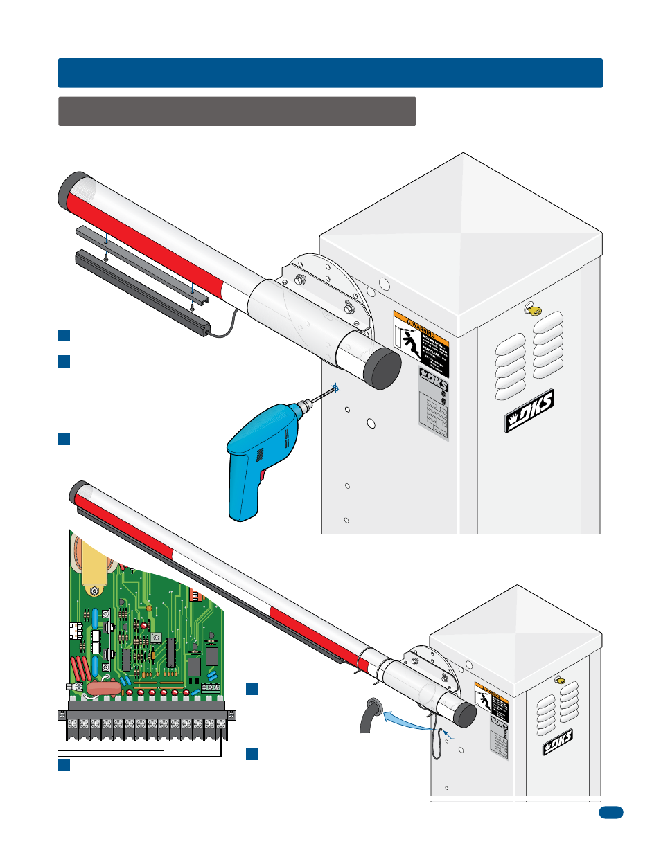
8.1 Contact Sensor (Reversing Edge)
SECTION 8 - OPTIONAL ACCESSORIES INSTALLATION
Connect wires to terminals 9 and
14 without interfering with any of
the operator’s moving parts.
CLA
SS
CER
TIF
IED
TO
CAN/C
SA
C2
2.2
NO.
24
7
CONF
ORM
S
TO
ANSI
/UL
-3
25
VEH
ICU
LAR
GA
TE O
PER
AT
OR
HP
533
82
MO
DE
L
SER
IAL
VOL
TS
PH
AS
E
AM
PS
60 H
z
MAX
GAT
E L
OA
D
Do
orK
ing
, In
c., I
ngle
woo
d,
CA
Wire Loop
Plastic
Grommet
1
2
3
4
5
6
Secure the wire to the arm and hub
using wire ties (not supplied). leave
a wire loop to allow the arm to
rotate freely.
Install a plastic grommet
(Not supplied) in the
hole to protect the wire
from chaffing on sharp
metal edges.
Reversing Edge Assembly
Wire T
ies
In addition to the electronic reversing device (ERD) an optional electric reversing edge may be installed offering additional
protection to the arm, operator and obstruction. Available from DoorKing to fit all arm lengths.
Turn operator power OFF.
Position the mounting channel at the end of
the barrier arm and secure to the bottom of
the arm using self-tapping metal screws
(not supplied). Slide the reversing edge into
the mounting channel.
Drill a 1/4-inch hole on the side of
the operator housing beneath the
operator arm shaft.