Input value for comparator i/o systems, Nput, Alue – CTI Products RCD Standard - Remote Comparator Display User Manual
Page 78: Omparator, I/o s, Ystems, Ven in section 9.3
MCN Remote Comparator Display
Appendix A
CTI Products, Inc.
Changing Status Message Text
68-10856-210
72
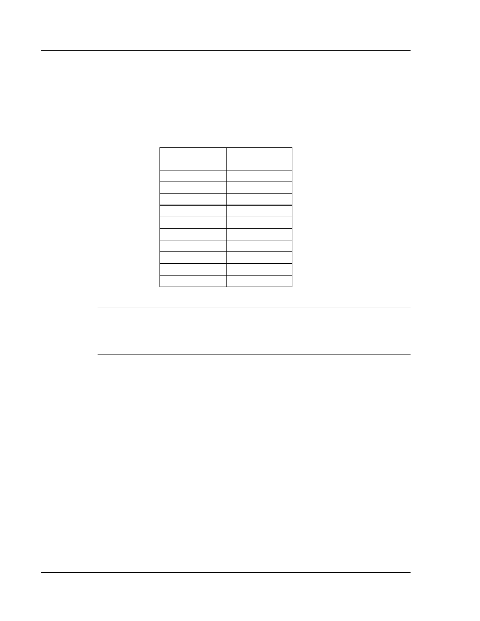
9.4.1 Input Value For Comparator I/O Systems
Each receiver’s status is described by a single byte of status information received
from the Comparator I/O Modules. The status information byte format is defined
in Table 4. Any value not shown in the table results in an ERROR status display
(“Err”). The “x” bits in the table indicate input value bits that can be either a 0 or
a 1, therefore both conditions of this bit must be accounted in separate text
definition lines of the MCNRCD.CFG file.
Bits
76 54 32 10
State
00 00 00 00
IDLE
00 00 0x 01
VOTE
00 00 01 00
RX
0x 01 0x 00
DISABLE
01 00 0x 00
FAIL
00 00 00 10
TX
00 00 0x 11
TX/VOTE
00 00 01 10
TX/RX
0x 01 0x 10
TX/DISABLE
01 00 0x 10
TX/FAIL
Table 4 - Input Value Format
Note: In Table 4, any bit position shown as a 1 is an active input signal and any
bit shown as a 0 is an inactive input signal. For the MCN system, all I/O signals
are active low, so any active input signal is low at the CIB or IOB I/O connector
and any inactive input signal is high at the CIB or IOB I/O connector.
From Table 4 you can see that one condition defines an IDLE state:
1.
00 00 00 00 : IDLE
For this IDLE state, the displayed text defined in MCNRCD.CFG must be a single
space. The color video attribute for this state must be 1F hex and the black and
white video attribute for this state must be 0F hex.
Two conditions define a VOTE state:
1.
00 00 00 01 : VOTE
2.
00 00 01 01 : VOTE + RX
Only one condition defines a RX state:
1.
00 00 01 00 : RX