Sub-category example – CTI Products RCD Standard - Remote Comparator Display User Manual
Page 102
MCN Remote Comparator Display
Appendix A
CTI Products, Inc.
Changing Status Message Text
68-10856-210
96
9.12.2.1 Sub-Category
Example
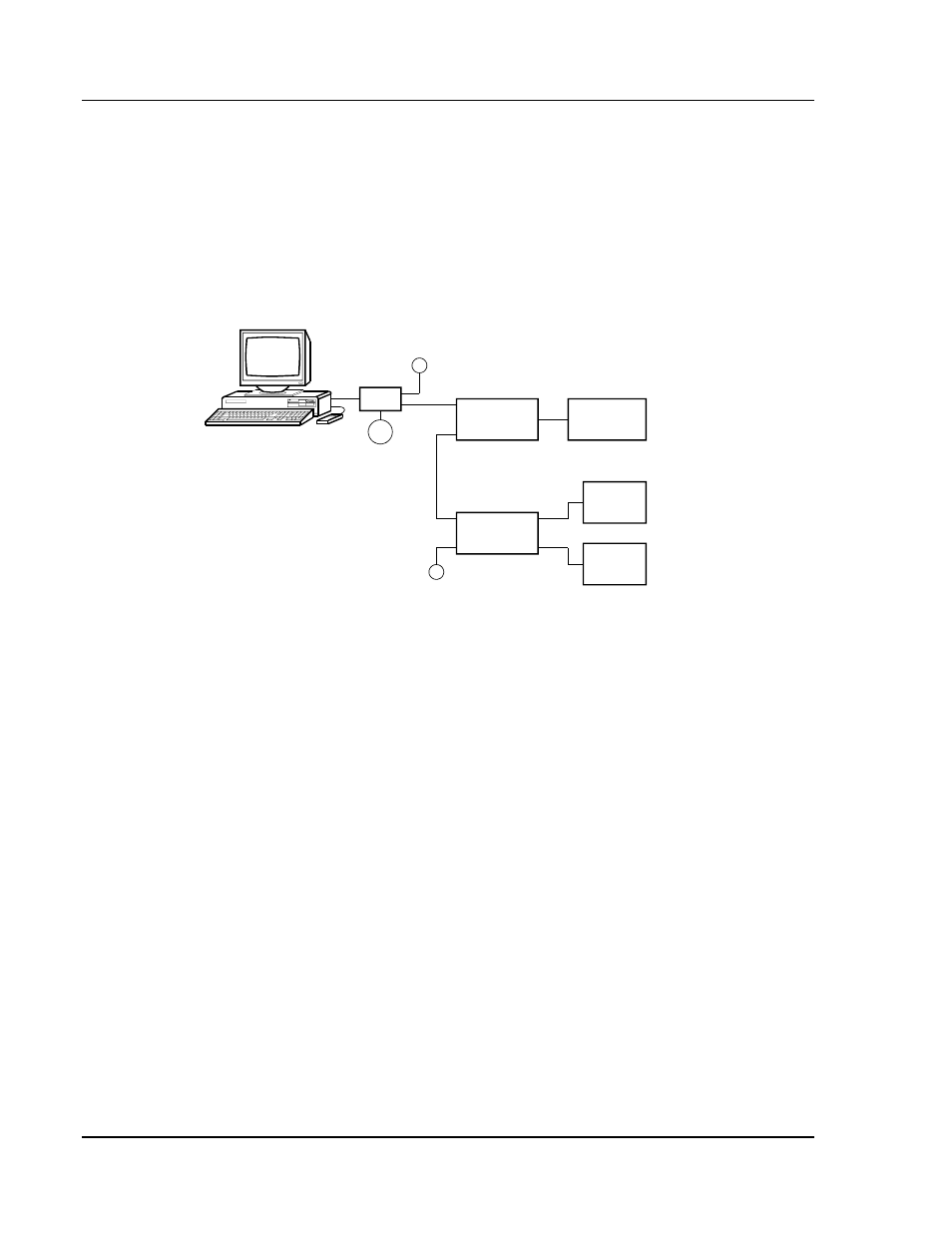
Suppose we have a MCN system like the one shown in Figure 39. In this system,
there are two MCN I/O modules being monitored and controlled by the PC, which
is running the MCNRCD software. Each module is connected to a different type
of I/O device. The Comparator I/O Module is connected to a RF receiver
comparator system and the Input/Output Control Module is connected to both
alarm inputs and control system inputs and outputs.
COM 2
COM 1
CA-80242-100
HIB
T
P/S
IN
OUT
IN
OUT
COMPARATOR
I/O
MODULE
GROUP 00 MODULE 0
IN
OUT
GROUP 00 MODULE 1
INPUT/OUTPUT
CONTROL
T
CONTROL
INPUTS &
OUTPUTS
ALARM
INPUTS
COMPARATOR
MODULE
Figure 39 - Sub-Category Example System
The MCNRCD.CFG file shown in Figure 38 shows the two categories defined for
this system. In this system, the Comparator I/O Module will use the category
DEFAULT. The Input/Output Control module will use the ALM-CTRL category.
This category includes the sub-categories for alarm input and control inputs. In
order for the correct status messages to be displayed for the Input/Output Control
module, the sub-category selector input must be properly set for each group of
inputs. The sub-category selector input for this example is the input that
corresponds with the FAIL status input signal of Table 2. For this system, any
alarm inputs must have their sub-category selector input left floating (no connect)
so that the selector bit is inactive. Any control inputs must have their sub-
category selector input pulled low so that the selector bit is active.