Fluid Components International GF90_GF92 User Manual
Page 74
FLUID COMPONENTS INTERNATIONAL LLC
http://www.fluidcomponents.com
GF Series Flow Meter Models GF90/GF92
70
Doc. No. 06EN003229 Rev. H
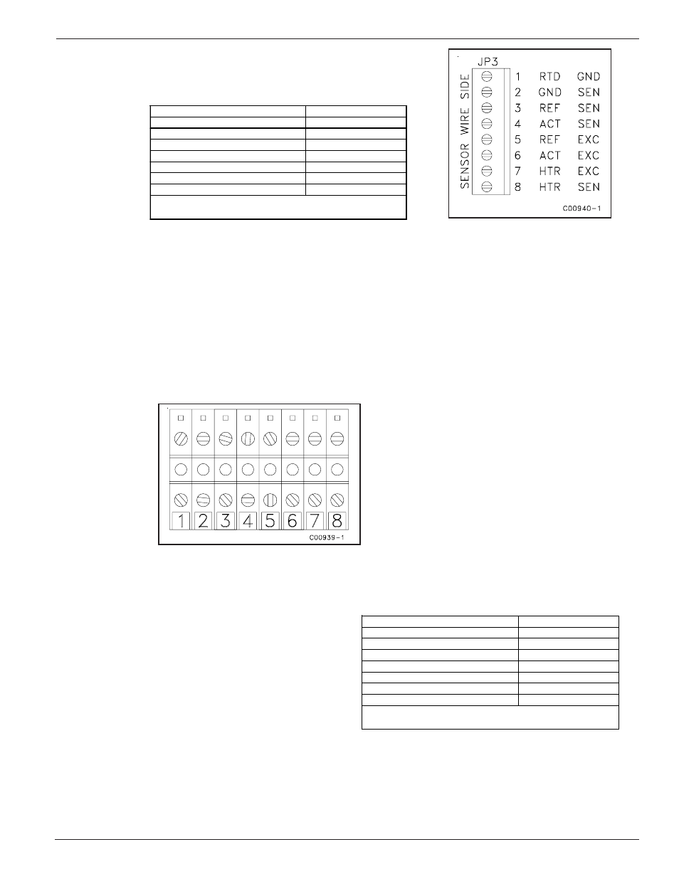
Table 13.
Resistance at JP-3 terminals after cable has
been disconnected for 15 minutes.
(This test will also verify cable continuity)
Figure 55. JP3 Terminal Plug
If the measured resistances correspond to Table 13 then the flow element is functioning properly. The
problem lies else where. Skip the rest of this section and proceed with the section, In-Depth
Troubleshooting - The flow transmitter. If the measured values do not correspond to Table 13 then a
problem exists in the flow element. For remote instruments, with a cable between the flow element and the
flow transmitter, the cable could be shorted or open. To isolate a problem with the cable, check the flow
element resistances at the terminal block located within the flow element (local) enclosure. Disconnect
the wires from the terminal block and measure resistances described below by touching the DMM test
leads to the terminal block screws. The measured resistances should correspond approximately to the
values in Table 14.
If the measured resistances correspond to Table 14 then the cable or wiring is defective. If the measured
values do not correspond to Table 14 then the Flow Element is defective. Contact customer service for
details on how to obtain another cable or flow element.
Figure 53.
VeriCal Flow Element
Enclosure Terminal Block
Table 14.
Resistance at probe terminals after cable has
been disconnected for 15 minutes
LUG OR PIN NUMBER
RESISTANCE
(7) HTR EXC TO (8) HTR RTN
110 – 118 OHMS
(4) ACT SEN TO (2) GND SEN
1.1K OHMS
(3) REF SEN TO (2) GND SEN
1.1K OHMS
(3) REF SEN TO (4) ACT SWEN
2.2K OHMS
(1) RTD GND TO (2) GND SEN
0 OHMS
(4) ACT SEN TO (6) ACT EXC
0 OHMS
(3) REF SEN TO (5) REF EXC
0 OHMS
NOTE: SHIELD TO GND AT TRANSMITTER BOARD
ONLY
LUG OR PIN NUMBER
RESISTANCE
(1) GND TO (7) HTR EXC
110 – 118 OHMS
(4) ACT SEN TO (2) GND SEN
1.1K OHMS
(3) REF SEN TO (2) GND SEN
1.1K OHMS
(3) REF SEN TO (4) ACT SWEN
2.2K OHMS
(1) RTD GND TO (2) GND SEN
0 OHMS
(4) ACT SEN TO (6) ACT EXC
0 OHMS
(3) REF SEN TO (5) REF EXC
0 OHMS
NOTE: SHIELD TO GND AT TRANSMITTER BOARD
ONLY