Wiring preparation, Wiring the instrument – Fluid Components International GF90_GF92 User Manual
Page 10
FLUID COMPONENTS INTERNATIONAL LLC
http://www.fluidcomponents.com
GF Series Flow Meter Models GF90/GF92
6
Doc. No. 06EN003229 Rev. H
Before the instrument is opened to install the wiring, FCI recommends that ESD precautions be
observed. See Page 11 for ESD instructions.
Wiring
Preparation
This section wires the transmitter inputs, outputs and interconnection cabling for the instrument.
Route the output wiring through the opposite port from the power wiring. The maximum gauge of
wire to use is 16 AWG. See Table 1 on Page 16 and Table 2 on Page 17 for the maximum
distance that wires can be run.
Only qualified personnel are to wire or test this instrument. The operator assumes
all responsibilities for safe practices while wiring or troubleshooting.
CAUTION:
ALERT: The instrument contains electrostatic discharge (ESD) sensitive devices. Use standard
ESD precautions when handling the flow transmitter.
Wiring the
Instrument
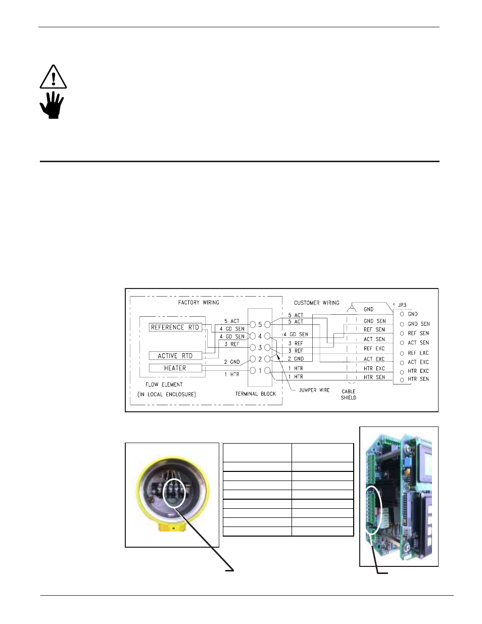
Wiring the Flow Element
Connect a shielded, 8 wire cable between the transmitter and the local enclosure terminal strip as
shown below. Be sure the shield (ground wire) is connected to JP3 GND along with the wire from
terminal block terminal 2. Do not connect the shield to the local enclosure (leave it floating).
Alternate 8 wire, ST98 Type Flow Element wiring shown in VeriCal and 2 point Averaging System
sections, see Operations Section 4.0.
Flow Element Terminal Block
(Be sure the jumper is in place
Terminal 2 to terminal 4.)
Local Enclosure Wiring Diagram
Flow Element Wiring Table
Flow Element
Transmitter
Terminal Block
JP3 (Terminal No.)
Terminal 5 (ACT)
ACT SEN (4)
Terminal 5 (ACT)
ACT EXC (6)
Terminal 4 (GND SEN) GND SEN (2)
Terminal 3 (REF)
REF SEN (3)
Terminal 3 (REF)
REF EXC (5)
Terminal 2 (GND)
GND (1)
Terminal 1 (HTR)
HTR EXC (7)
Terminal 1 (HTR)
HTR SEN (8)
Connector JP3