Customer wiring and serial communication option, Customer wiring – Fluid Components International GF90_GF92 User Manual
Page 24
FLUID COMPONENTS INTERNATIONAL LLC
http://www.fluidcomponents.com
GF Series Flowmeter Models GF90/GF92
20
Doc. No. 06EN003229 Rev. H
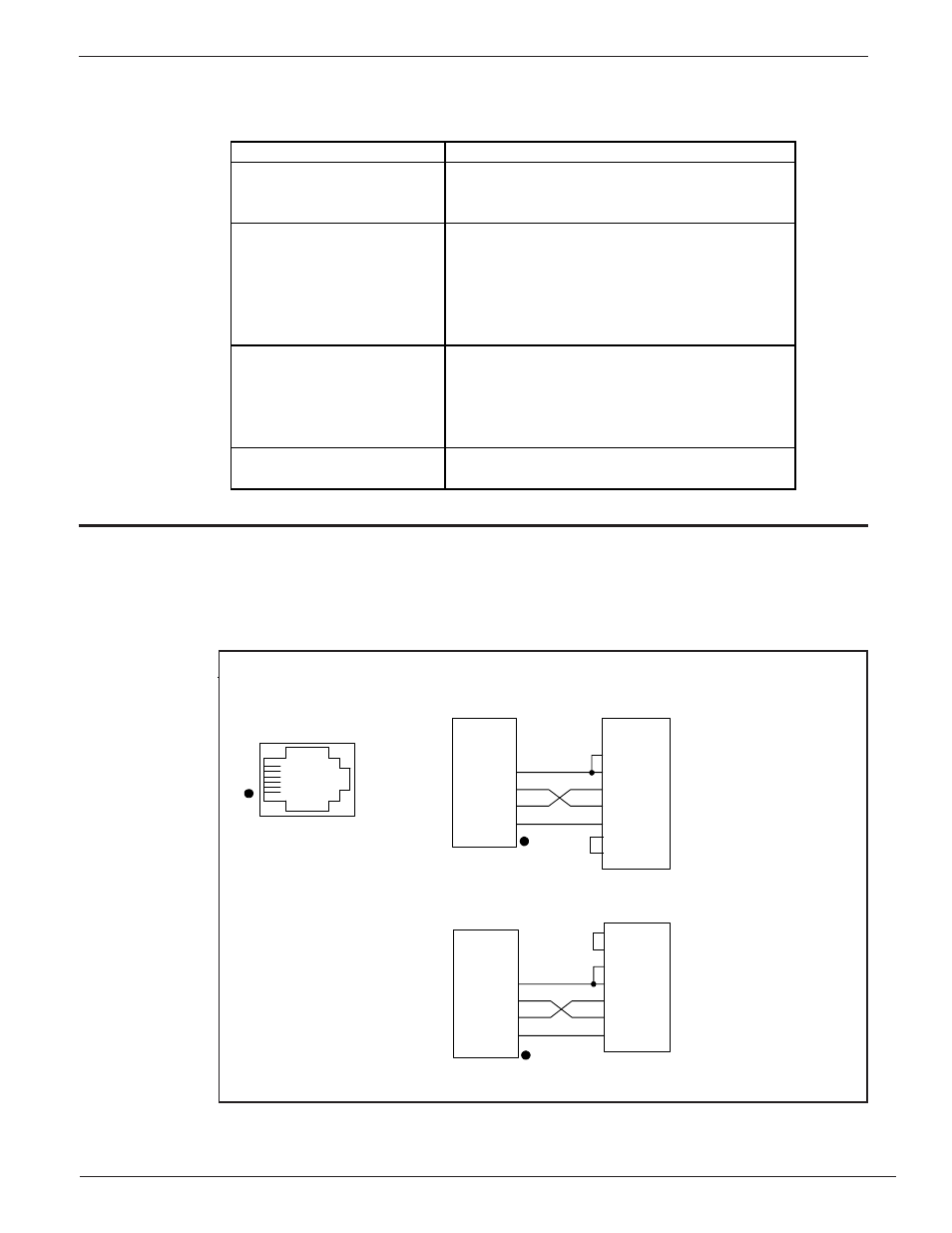
The RJ-12 (P3) connector on the top circuit board ( near the right side of the key pad) provides RS-232
communication with the user. An FC88 Communicator can be plugged in for periodic re-configuration
and/or diagnostics, or personal computer can be plugged in instead of the FC88 Communicator. This
connection is a RJ-12 communication (phone) jack. Figure 7 shows the connection between the serial
port and a host device. Figure 56 shows the wiring of the DB-9 connector.
6
5
4
3
2
1
Serial Port
RJ-12 Phone Jack
1
2
3
4
5
6
RJ-12 Pin
Description
DCD
DTR
TXD
RXD
GND
JUMPER
JUMPER
IBM PC
DB-9 Connector
Data Carrier Detect
Data Terminal Ready
Transmit Data
Receive Data
Ground
Jumper
Jumper
+5V
NC
DTR
TXD
RXD
GND
1
2
3
4
5
6
RJ-12 Pin
Description
JUMPER
JUMPER
DCD
DTR
TXD
RXD
GND
IBM PC
DB-25 Connector
Jumper
Jumper
Data Carrier Detect
Data Terminal Ready
Transmit Data
Receive Data
Ground
+5V
NC
DTR
TXD
RXD
GND
4
5
8
20
2
3
7
1
4
3
2
5
7
8
C00251-1
Serial
Communication
Option
(Hyper
Terminal Hook
Up)
JACK / NOMENCLATURE
DESCRIPTION
JP3 (Top Circuit Board)
RS-232 (EIA-232) Serial Port
Used in conjunction with equipment compatible
with an RS 232 (EIA-232) serial port. See
Chapter 4 for more details.
JP4
Relay Output 1
and
JP5
Relay Output 2
Factory pre-programmable relay contacts. Two
normally open and normally closed contacts are
available (double pole, single throw relay) per
jack. External relays can be connected to the
+EXT and -EXT pins in each jack.
Recommended relays are 18 Vdc, 0.
JP6
Analog Output
There are two factory pre-programmable signals
which are voltage and/or current. The 1AUX and
+20 V pin is a customer option for the use as a
dynamic correction factor. See Chapter 4 for
more information
JP7
RS485 (EIA-485) Serial Port
Used in conjunction with equipment compatible
with an RS 485 (EIA-485) serial port.
Customer
Wiring
Figure 7. Wiring Diagram, DB-9 and DB-25 PC Connectors
Jacks JP3 (top circuit board), JP4, JP5, JP6 and JP7 are for customer use and are described in Table 3.
Table 3. Customer Wiring