Fluid Components International GF90_GF92 User Manual
Page 48
FLUID COMPONENTS INTERNATIONAL LLC
http://www.fluidcomponents.com
GF Series Flow Meter Models GF90/GF92
44
Doc. No. 06EN003229 Rev. H
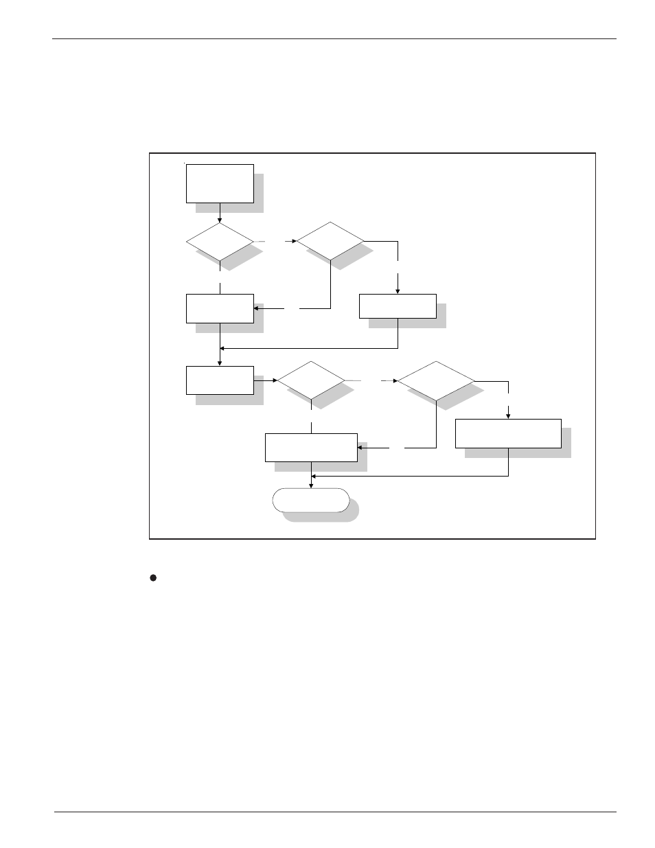
The flowmeter measures the applied current input, converts it to a digital value and makes a correction
to the measured flow rate. The corrected flow rate is used to drive the analog outputs and manipulate
the relays. The flow rate shown on the display is also the corrected value. Figure 30 charts the
process.
The auxiliary input port monitors the signal input level and converts it to a digital value. This digital
value can be displayed from menu level 2.4.3, the Auxiliary Test Input function.
Figure 30. Auxiliary Input Process
To view the digital representation of the current input:
1.
Apply a current to the auxiliary input as shown in Figure 29.
2.
From the Main menu press 2. The 2.0 PORT SETUP menu title will appear.
3.
Press 4, the Aux Input option.
4.
Press 3, the Test Input option. The digital representation of the current input is displayed on
the second line.
DR
Aux Input
Enb
Mode = DR?
DR
corr
= DR
DR
corr
= K
A
DR
Flow = f (DR
corr
)
Aux Input
Enb
Mode = Flow ?
Flow corr = Flow
Flow corr = K
A
Flow
YES
NO
NO
YES
YES
YES
NO
C00548-1
Output
Flow
corr
NO