Fluid Components International GF90_GF92 User Manual
Page 61
Doc. No. 06EN003229 Rev. H
57
GF Series Flow Meter Models GF90/GF92
FLUID COMPONENTS INTERNATIONAL LLC
http://www.fluidcomponents.com
11. Repeat steps 8 through 10 for 75 psig, 50 psig and 25 psig. The recorded values for flow temperature
and pressure are the instruments in-situ baseline calibration readings. All future verification readings
will be compared to these baseline values and should be within 2 % of these indicated readings.
12. The initial baseline calibration readings can be compared to the factory Verical calibration readings. If
the local atmospheric pressure is within 0.50 psi of atmospheric pressure during the factory Verical
calibration (located on the factory calibration sheet). The readings should be within 5 %.
13. Return the instrument electronics to the normal operation mode by pressing the “Home” key twice and
then pressing the no. “1” key. Place probe assembly back into the correct location in the center of the
process piping as indicated in the installation section of the operation manual. Return to normal
operation group if VeriCal group differs from normal operation group.
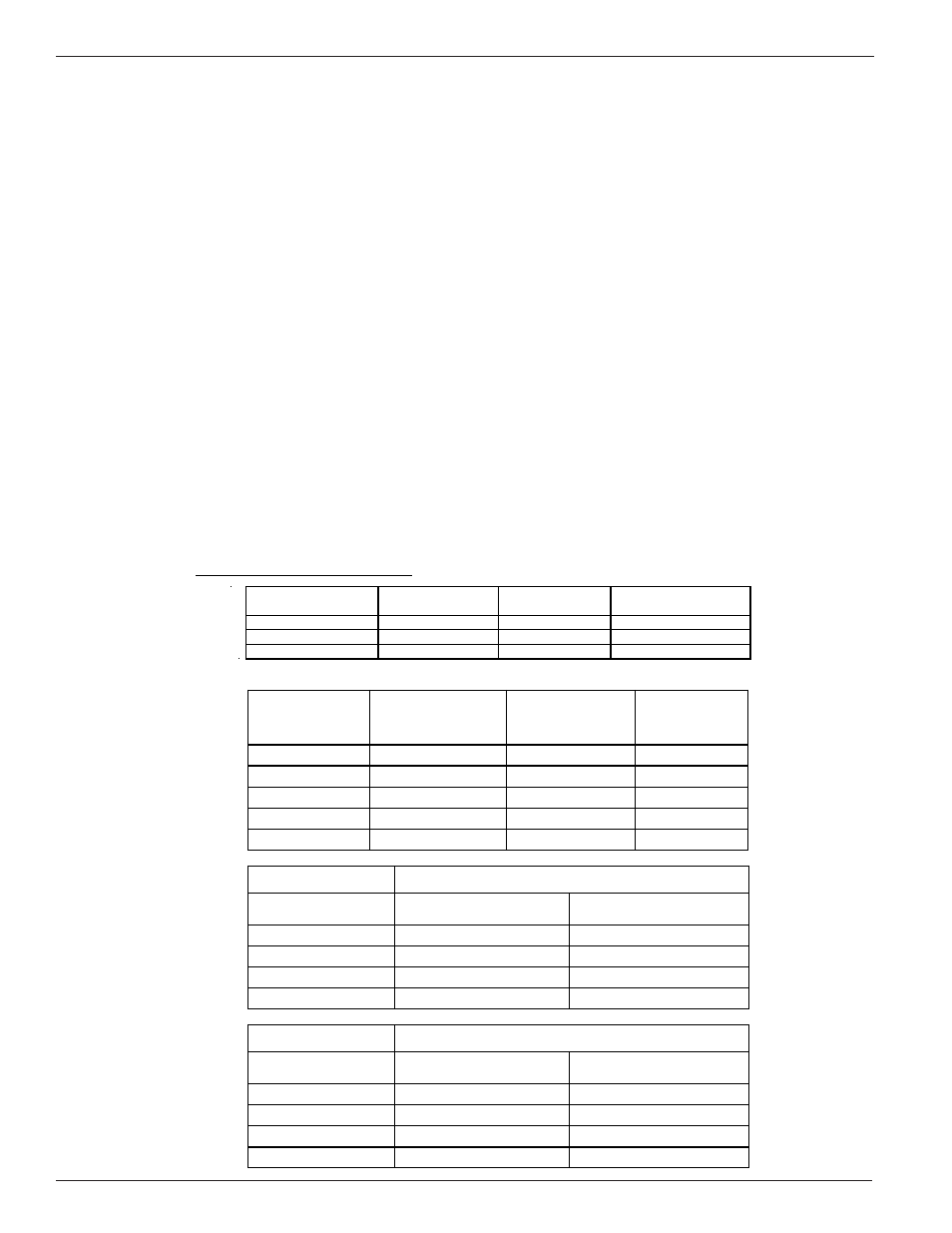
Calibration Verification (example)
C u s to m e r
O rd e r:
C 0 2 4 0 5 7
E q u ip . N o .:
C a l. D u e D a te
C u s to m e r:
E L -0 2 9
9 -1 2 -0 9
D a te : 0 2 -1 9 -0 9
E L -3 8 3
7 -2 8 -0 9
S e ria l N o .:
2 4 4 1 1 0
V eriC al
In dicated
Pressu re,
psig
P ressure
T ran sdu cer m A
O utp ut
In dicated F lo w
(SF PS )
In dicated
T em perature
D eg. F
100
29.96 72.4
75.00
34.25 74.2
50.00
22.15 74.7
25.00
10.55 75.3
0.000
0.000 78.3
Field B aseline
D ate:
In dicated
Pressu re, p sig
In dicated F lo w
(SF PS )
In dicated T em p .
Field C heck 1
D ate:
In dicated
Pressu re, p sig
In dicated F lo w
(SF PS )
In dicated T em p .
Recommended Procedure with Pressure Transducer
The pressure transducer is located in the VeriCal Regulator Assembly box. The transducer is wired to the
electronics assembly as shown in page 58.
The pressure transducer option provides a flow, temperature and pressure indication on the GF electronics
display. These parameters are accessed through the 7.4 menu.
The verification procedure is the same as the steps outline in the previous section (without pressure
transducer) steps 1 - 13. The only difference is that flow, temperature and pressure reading are all available
on the GF electronics display. The analog gauge mounted in the Regulator Assembly box can be used as a
caparison to the pressure transducer output as indicated on the GF electronics display.
FCI Certificate
For Customer Input Records