Chapter 4 ~ operation, Operation – Fluid Components International GF90_GF92 User Manual
Page 31
Doc. No. 06EN003229 Rev. H
27
GF Series Flow Meter Models GF90/GF92
FLUID COMPONENTS INTERNATIONAL LLC
http://www.fluidcomponents.com
The instrument has been configured and calibrated to customer specifications. Each instrument
contains distinct operating limits and units of measurement. This chapter will show how to determine
and manipulate the configuration of the instrument.
ALERT:
The flow transmitter contains electrostatic discharge (ESD) sensitive devices. Use
standard ESD precautions when handling the flow transmitter. See Chapter 3, Installation
for ESD details.
4. Operation
Introduction
Start Up
Procedure
Operation
1. After the wiring has been verified, apply power to the flowmeter. (No special instructions for
instrument shutdown; turn operating power off.)
2. Then wait 10 minutes for warm-up. During this period the flowmeter may indicate high flow.
3. After power up the instrument automatically enters the flow metering mode and the display sets to
normal operation.
Display
The flowmeter contains a 4 x 20 character LCD display. Flow rate, temperature, and system status are
all accessible through the display.
Initialization Window
When power is applied to the flowmeter the display will briefly show the initialization window. See
Figure 15.
Figure 15. Initialization Window
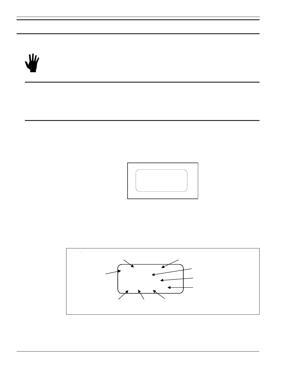
Normal Mode Window
The flowmeter upon power up defaults to the normal mode of operation and begins to display the flow
rate, the temperature, the total flow (if enabled ) and the current system status. The Normal Operation
display is shown in Figure 16.
CH1: 5056.3 SCFM
CH2: 71.2 °F
435226 SCF
(grp1)(ed)(norm)(m)
Output
Channel #
Flow Rate
Temperature
Sample
Rate
Σ =
Mode
Relay
Status
Group #
Totalizer
C00239-2
Flow Units
Figure 16. Normal Operation Display
FLUID COMPONENTS INC
Initializing
Wait, Please
V4.20 Dec 16 2003
C00238-2