Fluid Components International GF90_GF92 User Manual
Page 34
FLUID COMPONENTS INTERNATIONAL LLC
http://www.fluidcomponents.com
GF Series Flow Meter Models GF90/GF92
30
Doc. No. 06EN003229 Rev. H
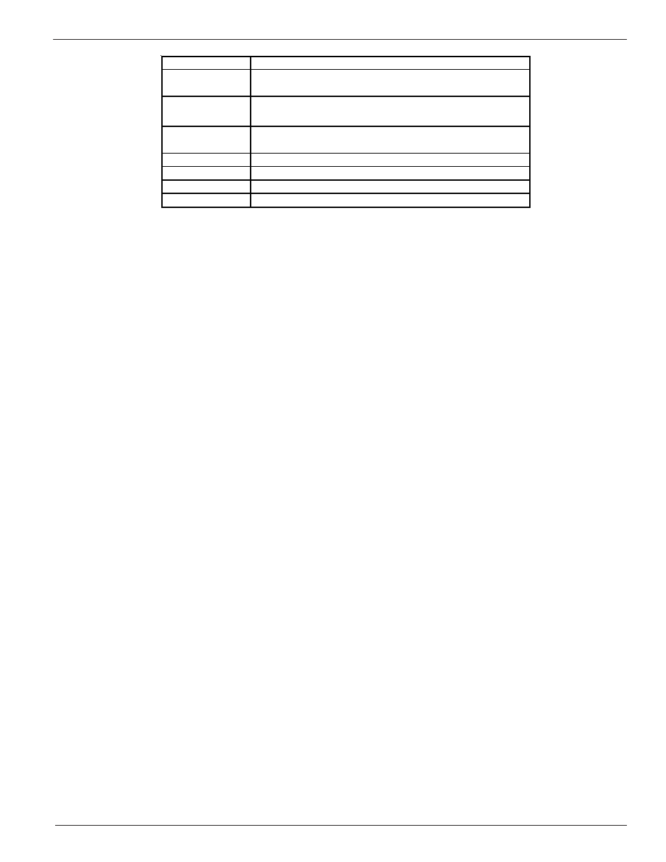
Table 5. Menu Functions
The Port Setup, Display Setup and Miscellaneous groups is where most activity is concentrated. The
Verify, Diagnostics, Calibration and Normalize Board groups are used primarily for diagnostics and
factory calibration.
Normal Operation
The flowmeter upon power up defaults to this mode. During normal operation the flow rate and the
temperature is displayed. The total flow is displayed if it is enabled and few system configuration
parameters are shown. Figure 16 is the Normal Operation display.
The first and second lines contain the current flow rate and temperature. The total flow is displayed on
the third line only if it is enabled. The last line contains the current Group number (see the Multiple
Groups section in Advanced Features), the relay status, the mode of operation and the sample rate.
The relays status shows either e (energized) or d (de-energized). The letters correspond to the first and
second relays, respectively. The mode of operation is norm for normal, auto for Auto-Select or link for
Link Groups. (See Advanced Features for explanation of these modes). The sample rate is slow (s),
medium (m) or fast (f).
GROUP NAME
FUNCTION
Port Setup
Sets analog outputs, set relay switch points and configure
the auxiliary input.
Display Setup
Sets the units of measure for the displayed flow rate,
temperature and total flow. Sets the sample rate.
Miscellaneous
Sets the current calibration group. Configures the
Corrector. Sets the user Password.
Verify
Displays system variables to the screen.
Diagnostics
Factory use only.
Calibration
Displays Delta R in Ohms.
Normalize Board Factory use only.