Alert – Fluid Components International GF90_GF92 User Manual
Page 11
Doc. No. 06EN003229 Rev. H
7
GF Series Flow Meter Models GF90/GF92
FLUID COMPONENTS INTERNATIONAL LLC
http://www.fluidcomponents.com
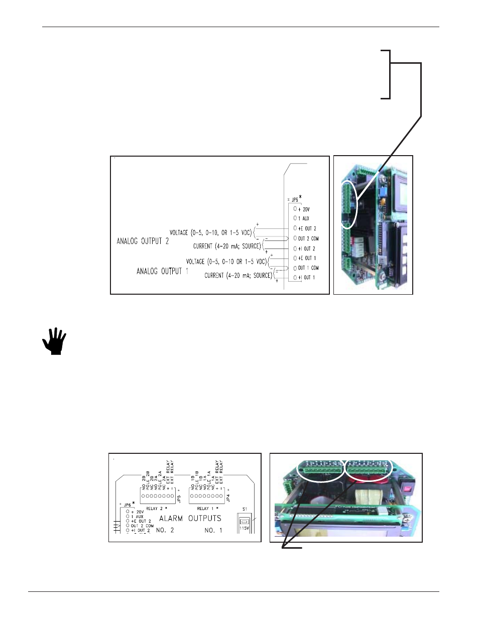
Analog Output 2 is connected in a similar manor as Analog Output 1. ( For Voltage Output:
0 - 5, 0 - 10 or 1 -5 Vdc; connect a positive wire to + E OUT2 and a negative wire to
OUT 2 COM. For Current Output: 4 - 20 mA; connect a positive wire to + I OUT2 and a
negative wire to OUT 2 COM.)
For Voltage Output: 0 - 5, 0 - 10 or 1 -5 Vdc; connect a positive wire to + E OUT
and a negative wire to OUT COM.
Analog Output
Plug Location
Wiring the Instrument’s Signal Output to the Customer Application:
Alert:
Either voltage or current from the Analog Outputs can be connected to the customer
application, not both. (Example: Voltage and current from analog output 1 cannot be
connected.) However, one Analog Output can be wired for current and the other
Analog Output can be wired for Voltage.
Customer Connections Analog Output Diagram
For Current Output: 4 - 20 mA; connect a positive wire to + I OUT and a negative wire
to OUT COM.
Wiring the Output Relays:
The instrument contains two sets of alarm output relays (connectors JP4 Relay Output 1, and JP5
Relay Output 2). They can be wired by the customer. (NO = Normally Open, NC = Normally
Closed, Pole = Common)
Output Relay Wiring Diagram
Connectors JP5 and JP4