4 adding rectifier shelves, Figure 38 — can bus termination, Figure 39 — can out connection – Alpha Technologies Cordex CXPS-M 48_24-1200_600A User Manual
Page 56
9400004-J0 Rev B
54
9.4 Adding Rectifier Shelves
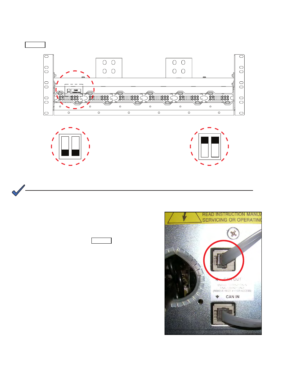
The CAN bus provides a communication path between the controller and rectifiers. In a single bay, the CAN bus
cabling is daisy-chained from the shunt mux, if installed, to the bottom rectifier shelf. The cable is then daisy-
chained from the bottom shelf, to higher shelves, in sequence. At the last shelf, termination is enabled—see
CAN termination enabled
CAN termination disabled
Figure 38 — CAN bus termination
1. Remove the left most rectifier in the top shelf of the
existing bay. (Refer to the Rectifier Shelf manual for
the removal and re-insertion procedure.)
2. Flip the DIP switches from Termination Enabled to
Termination Disabled—see Figure 38.
3. Replace the rectifier.
4. Connect the CAN bus cable to the CAN OUT
connector of the top rectifier shelf of the expansion
bay.
Figure 39 — CAN OUT connection
NOTE:
If your system has redundant rectifiers, it is recommended to power off the left most
rectifier in the top shelf of the existing bay during this procedure.