Table e — cable size equivalents (awg to metric), Table f — recommended torque values, 3 recommended torque values – Alpha Technologies Cordex CXPS-M 48_24-1200_600A User Manual
Page 40: 4 cabling layout
9400004-J0 Rev B
38
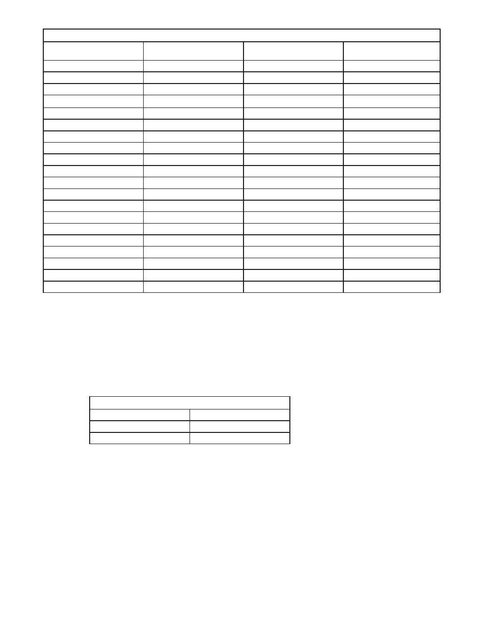
Table E — Cable size equivalents (AWG to Metric)
Cable size (see notes 1
and 2)
Circular mils
Square millimeters
Equivalent metric cable
20 AWG
1020
0.519
1
18 AWG
1624
0.8232
1
16 AWG
2583
1.309
1.5
14 AWG
4107
2.081
2.5
12 AWG
6530
3.309
4
10 AWG
10380
5.261
6
8 AWG
16510
8.368
10
6 AWG
26250
13.30
16
4 AWG
41740
21.15
25
2 AWG
66370
33.63
35
0 AWG (or 1/0)
105600
53.48
50 or 70
00 AWG (or 2/0)
133100
67.42
70
0000 AWG (or 4/0)
211600
107.2
120
313 MCM (or kcmil)
313600
159
150 or 185
350 MCM (or kcmil)
350000
177.36
185
373 MCM (or kcmil)
373700
189
185 or 240
500 MCM (or kcmil)
500000
253.36
300
535 MCM (or kcmil)
535300
271
300
750 MCM (or kcmil)
750000
380.00
400
777 MCM (or kcmil)
777700
394
400
t
6.1.3 Recommended Torque Values
Recommended torque values for connection to the power system:
x
Clear hole connections (nut and bolt)
x
PEM studs
x
PEM threaded inserts
x
Thread formed connections (in copper bus bar)
Table F — Recommended torque values
1/4"
8.8 ft-lbs
3/8"
32.5 ft-lbs
1/2"
73 ft-lbs
SAE Grade 5 rating is required for these torque values.
6.1.4 Cabling Layout
The cabling at the time of installation is straightforward.
x
The AC cables for the rectifiers connect to the shelves on both sides, and are brought down from
the top of the frame to the rectifier shelves.
x
The battery cables and the external battery return bar (if equipped) connect to the bay at the top
rear.
x
The load cables to the distribution modules enter the bay through the top.
x
The load return cables connect to the distribution modules or an external battery return bar
x
All signaling wires (for example, alarms from the CXC Controller) interfacing with the outside world
exit the frame through the top or through the conduit opening.