Alpha Technologies Cordex CXPS-M 48_24-1200_600A User Manual
Page 28
9400004-J0 Rev B
26
3.12.2 Front Panel LEDs
Three LEDs are located on the front panel: one green, one yellow, and one red. These LEDs are used to display
the alarm status of the power system, controller progress and status during startup, and file transfers.
Alarm conditions
Only one LED light is illuminated at a time during alarm conditions. Each LED light corresponds to a specific
alarm. A built-in audio speaker sounds an intermittent tone during active alarms.
Illuminated LED
Alarm
Green
OK, no alarms
Yellow
Minor alarm, no major alarms
Red
Major alarm
Progress and status indication
The LED lights are also used in the following situations:
• Base unit validation—all three LEDs illuminate
• File transfer—red LED illuminates
3.12.3 Front Panel Reset Button
Use the controller LCD to select the RESET menu item before pressing the reset button. Refer to the software
manual for details.
Pressing the reset button, on the front panel, restarts the CXC microprocessor. It takes approximately 15 seconds
before the display reappears after pressing the reset button (Figure 15).
3.12.4 Network Connection and Remote Communications
The Cordex system can be set up, monitored, and tested via an Ethernet 10/100 Base-T serial data connection.
The controller includes a web server that provides easy set up and monitoring over an Internet connection to a
web browser.
Craft port
Local access to the CXC is possible through a front panel RS-232 serial port (Figure 15), using a null modem
cable. The communication protocol supports a web interface (Microsoft® Internet Explorer 6 or greater). The
remote screen display is an enhanced version of the CXC front panel display.
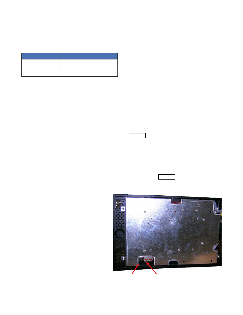
Ethernet
port
CAN
port
Ethernet port
An Ethernet port is located inside the front panel.
This port is designed to connect the controller to
a user supplied TCP/IP network. Use a standard
RJ-45 jack with a standard network cable.
The Ethernet port can be used for local access,
for example to a laptop computer. Use a standard
network crossover cable for the connection.
Internal CAN Bus
A CAN bus is used to transmit all alarm and con-
trol functions between the controller, shunt mux
and the rectifier shelves.
A single CAN Serial port, for communications with
other distribution modules is located inside the
front panel next to the Ethernet port.