Alpha Technologies Cordex CXPS-M 48_24-1200_600A User Manual
Page 47
45
9400004-J0 Rev B
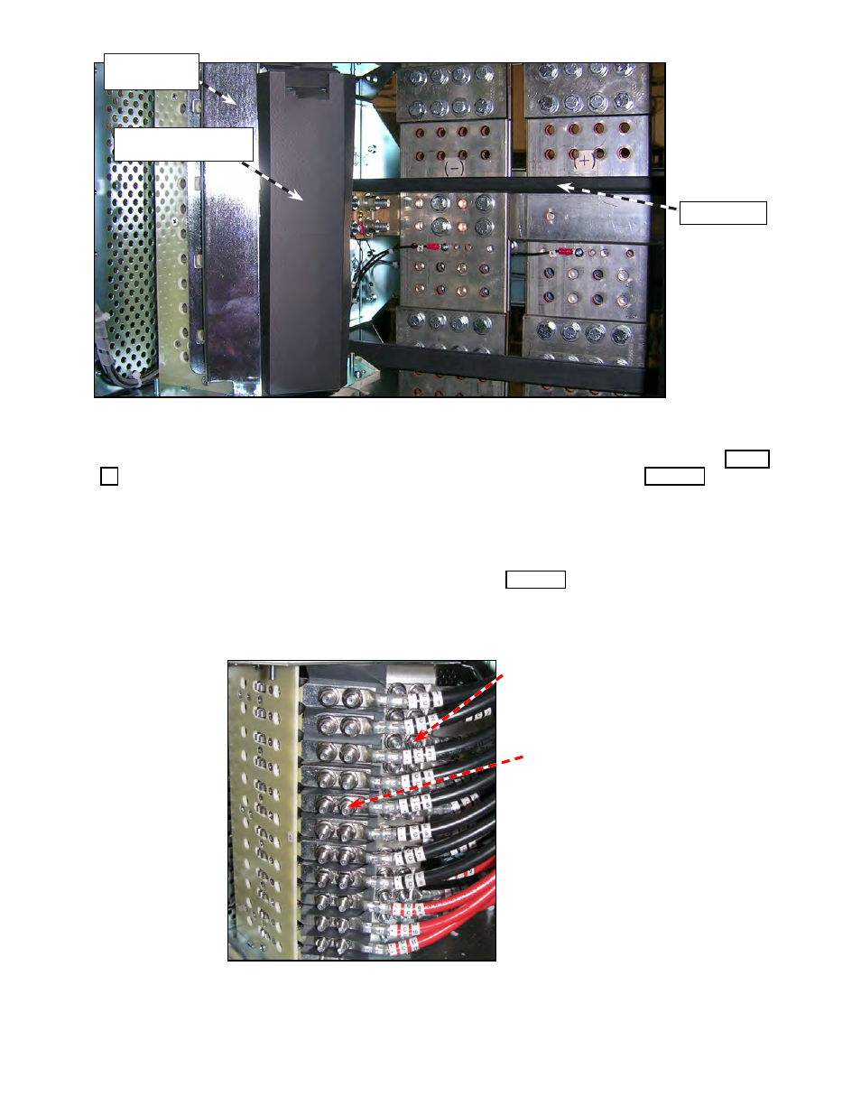
Figure 29 — Breaker distribution module before load cables are installed
Load ("hot") connections
Load (return) – Connect here
or connect to external return
bus bar, if installed.
Figure 30 — Breaker load cable and return connections
Cable tie bar
Protective "hot" termi-
nal cover
Circuit breaker
guard
4. Connect the load return cables to the return side of the each breaker position starting at the bottom(Figure
30). Alternatively, connect the load return cables to the external battery return bus bar (Figure 26).
5. Connect the primary voltage load cables to circuit breaker positions from the bottom up, in the bottom
distribution module.
6. For the dual voltage option, connect the secondary voltage load cables to circuit breaker positions from the
bottom up, in the bottom distribution module.
7. Tie cables to the cable tie bars at the back of the power system (Figure 29 shows the location).
8. Add additional circuits going from bottom to top tying in the additional layers on top of the previous layers.